Pneumatic tire

A technology of pneumatic tires and tires, which is applied to tire parts, tire tread/tread pattern, transportation and packaging, etc., to achieve the effect of improving performance on snow and ice

Inactive Publication Date: 2015-07-08
THE YOKOHAMA RUBBER CO LTD
View PDF11 Cites 11 Cited by
  • Summary
  • Abstract
  • Description
  • Claims
  • Application Information

AI Technical Summary

Problems solved by technology

[0003] In addition, the technology described in Patent Document 2 is known. Although it is a truck tire used for trucks, buses, etc., the pneumatic tire has a tread pattern similar to that of the present invention.

Method used


Image

  • Pneumatic tire
  • Pneumatic tire
  • Pneumatic tire

Examples


Embodiment 1

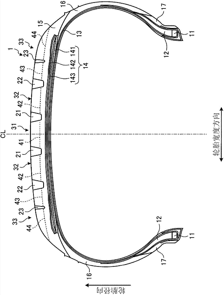
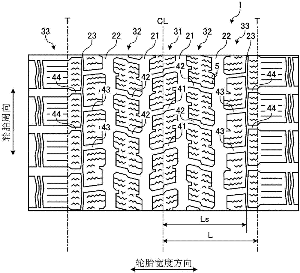
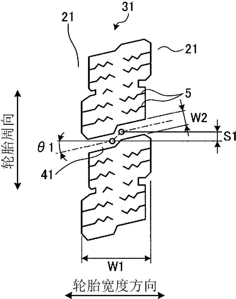
[0093] The pneumatic tire 1 of Example 1 has Figure 1 ~ Figure 4 the documented structure. The pneumatic tires 1 of Examples 2 to 13 are modified examples of the pneumatic tire 1 of Example 1. In addition, the distance L from the tire equatorial plane CL to the ground contact edge T is L=80 mm. In addition, the maximum groove depth H of the outermost circumferential main groove 22 is H=13.5 mm.

[0094] The pneumatic tire of the conventional example has Figure 8 structure shown. The pneumatic tire of the comparative example has Figure 9 structure shown.

[0095] As shown in the test results, it can be seen that in the pneumatic tires 1 of Examples 1 to 13, the uneven wear resistance performance, performance on ice and performance on snow of the tire were improved.

[0096] Symbol Description

[0097] 1: Pneumatic tire

[0098] 5: Three-dimensional groove

[0099] 11: Bead core

[0100] 12: Bead core

[0101] 13: Ply

[0102] 14: belt layer

[0103] 15: Tread ru...


PUM


Abstract

This pneumatic tire (1) is provided with at least four circumferential main grooves (21, 22) extending in a tire circumferential direction, and a plurality of land portions (31-33) formed by being demarcated by the circumferential main grooves (21, 22). The pneumatic tire is further provided with a first lug groove (41) penetrating the center land portion (31) in a tire width direction, a circumferential narrow groove (23) disposed in the shoulder land portion (33) and extending in the tire circumferential direction, a second lug groove (43) extending inward from the circumferential narrow groove (23) in the tire width direction and open to the outermost circumferential main groove (22), and a third lug groove (44) extending outward from the circumferential narrow groove (23) in the tire width direction, open to a tread end, and disposed to be positionally displaced from the second lug groove (43) in the tire circumferential direction. The first lug groove (41) has a bent shape and is open with a see-through structure to the right and left circumferential main grooves (21, 22) that demarcate the center land portion (31).

Description

technical field [0001] The present invention relates to a pneumatic tire, and more particularly, to a pneumatic tire capable of improving the performance on ice and on snow of the tire. Background technique [0002] In the case of studless tires for small trucks, there is a problem of improving the performance on ice and snow of the tire, and traction patterns having a plurality of block rows having grooves are currently used. As a conventional pneumatic tire related to this problem, the technique described in Patent Document 1 is known. [0003] Also, the technique described in Patent Document 2 is known, and although it is a truck tire used for trucks, buses, etc., this pneumatic tire has a tread pattern similar to that of the present invention. [0004] prior art literature [0005] patent documents [0006] [Patent Document 1] Japanese Patent Laid-Open No. 2004-26158 [0007] [Patent Document 2] Japanese Patent Laid-Open No. 2011-31885 Contents of the invention ...

Claims


Application Information

Patent Timeline
Patent Type & Authority Applications(China)
IPC IPC(8): B60C11/04B60C11/00B60C11/11B60C11/12B60C11/13
CPCB60C2011/1213B60C11/0306B60C11/1236B60C2011/1254B60C11/1218B60C2011/0348B60C2011/0346
Inventor 永吉胜智
Owner THE YOKOHAMA RUBBER CO LTD
Why Eureka
Try Eureka