
Pneumatic tire

A technology of pneumatic tires and tires, which is applied to tire parts, tire treads/tread patterns, transportation and packaging, etc. It can solve the problems of performance degradation and difficulty in balancing, increase rigidity, improve performance on ice and snow Performance, the effect of improving handling stability

Active Publication Date: 2012-07-04
THE YOKOHAMA RUBBER CO LTD
View PDF5 Cites 1 Cited by
  • Summary
  • Abstract
  • Description
  • Claims
  • Application Information

AI Technical Summary

Problems solved by technology

However, if the ratio of the groove area in the tread portion is simply reduced, the on-snow performance will be reduced accordingly.
That is, performance on ice and performance on snow are in a contradictory relationship, and it is extremely difficult to balance both

Method used


Image

  • Pneumatic tire
  • Pneumatic tire
  • Pneumatic tire

Examples


Embodiment 1

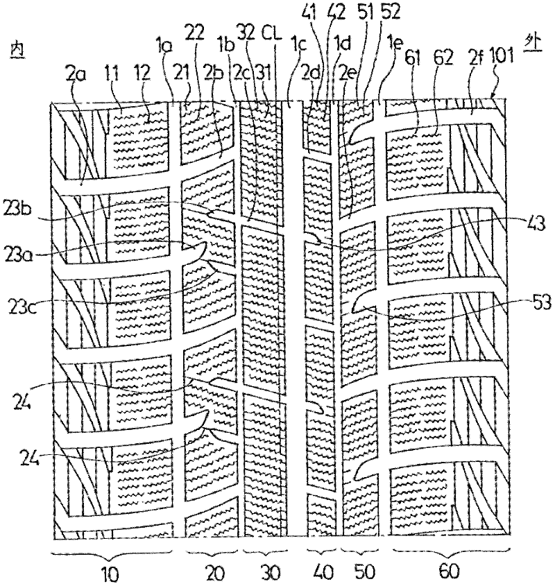
[0065] The tire of Example 1 has image 3 In the tread pattern, the inclination angle θa of the first closed groove 23a is set to -17°, and the inclination angles θb and θc of the second closed grooves 23b and 23c are respectively set to +15°. The tire of Example 2 has Figure 8 The tread pattern has the same pattern as in Example 1, except that the first closed groove 23a is arranged at a position shifted from the transverse groove 2a that defines the blocks 11 of the block row 10 of the shoulder in the tire circumferential direction. structure.

[0066] For comparison, prepare to have the same image 3 Tires of Comparative Examples 1 and 2 with similar tread patterns. That is, the tire of Comparative Example 1 has Figure 10 The tread pattern of each block 21 is provided in each block 21 instead of providing the closed grooves 23a to 23c, and a transverse groove that crosses each block 21 is provided, and each block 21 is subdivided in the tire circumferential direction....

Embodiment 3

[0080] The tire of Example 3 has Figure 7 In the tread pattern, the inclination angle θa of the first closed groove 23a is set to -17°, and the inclination angles θb and θc of the second closed grooves 23b and 23c are respectively set to +15°. The tire of Example 4 has Figure 9 The tread pattern has the same pattern as that of Example 3, except that the first closed groove 23a is arranged at a position shifted from the transverse groove 2a that defines the blocks 11 of the block row 10 of the shoulder in the tire circumferential direction. structure.

[0081] For comparison, prepare to have the same Figure 7 Tires of Comparative Examples 3 and 4 with similar tread patterns. That is, the tire of Comparative Example 3 has Figure 12 The tread pattern of each block 21 is provided in each block 21 instead of providing the closed grooves 23a to 23c, and a transverse groove that crosses each block 21 is provided, and each block 21 is subdivided in the tire circumferential dir...


PUM


Abstract

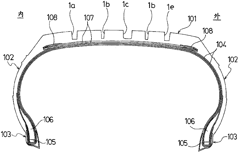
A pneumatic tire improved in on-ice performance and on-snow performance in good balance. The pneumatic tire includes a tread portion extending in a tire circumferential direction and forming a ring shape, a pair of sidewall portions on both sides of the tread portion, respectively, and a pair of bead portions on inner sides of the sidewall portions in a tire radial direction, respectively. The tread portion includes a plurality of longitudinal grooves extending in the tire circumferential direction and a plurality of lateral grooves extending in a tire width direction. The longitudinal and lateral grooves define a plurality of block rows each including a plurality of blocks. Each of the plurality of blocks included in at least one of the block rows includes at least three closed grooves including at least one first closed groove and at least one second closed groove.

Description

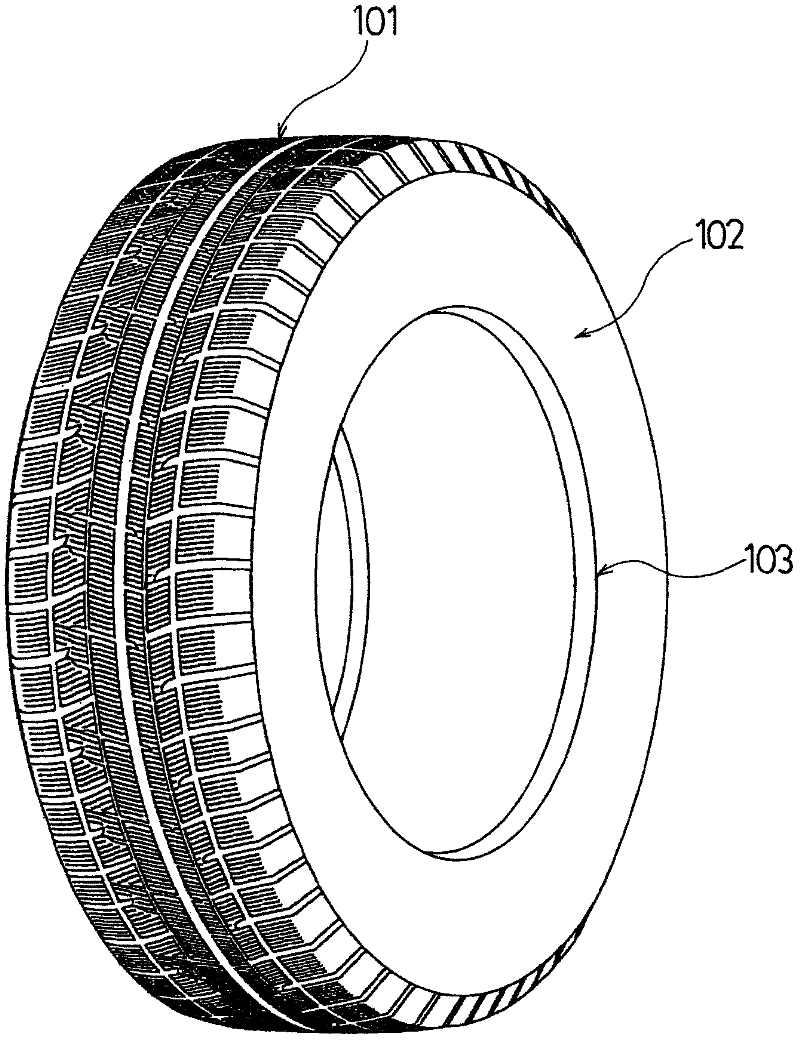
technical field [0001] The present invention relates to a pneumatic tire suitable for use in winter, and more specifically, to a pneumatic tire capable of improving ice performance and snow performance in a balanced manner. Background technique [0002] Conventionally, in pneumatic tires used in winter, represented by studless tires, a plurality of longitudinal grooves extending in the tire circumferential direction and a plurality of transverse grooves extending in the tire width direction are provided in the tread portion, and the tires pass through these longitudinal grooves. And the lateral grooves define a plurality of blocks, and each block is provided with a plurality of sipes extending in the tire width direction (for example, refer to Patent Document 1). [0003] In such a pneumatic tire used in winter, both performance on ice and performance on snow are required. In general, in order to improve performance on ice, a tread pattern is used that reduces the ratio of ...

Claims


Application Information

Patent Timeline
Patent Type & Authority Applications(China)
IPC IPC(8): B60C11/03
CPCB60C2011/0383B60C2011/1213B60C2011/1254B60C11/0304B60C2011/1227B60C11/12B60C11/11B60C2011/0381
Inventor 长安政明古泽浩史
Owner THE YOKOHAMA RUBBER CO LTD
Learn More