Cage rotor comprising a deformable bearing

A cage-type rotor and rotor technology, which is applied in the field of rotor combination laminations and manufacture of cage-type rotors, can solve problems such as increased resistance, and achieve the effects of small unbalance, small wear, and low resistance

Active Publication Date: 2015-07-08
SIEMENS AG
View PDF5 Cites 2 Cited by
  • Summary
  • Abstract
  • Description
  • Claims
  • Application Information

AI Technical Summary

Problems solved by technology

This overcomes the problem that the electrical resistance between the shorting ring and the rod increases when the rod cannot follow the movement of the shorting ring that shrinks during cooling

Method used


Image

  • Cage rotor comprising a deformable bearing
  • Cage rotor comprising a deformable bearing
  • Cage rotor comprising a deformable bearing

Examples


Embodiment Construction

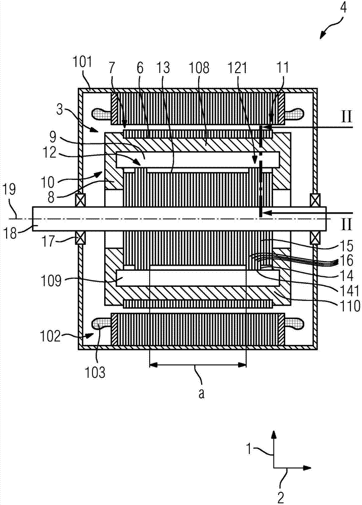
[0064] figure 1A first embodiment of an electric machine 4 comprising a first embodiment of a cage rotor 3 is shown. The electric machine 4 is an asynchronous machine and has a housing 101 in which a stator 102 is arranged. The stator 102 has a winding 103 . The cage rotor 3 is fastened on a shaft 18 , which is mounted rotatably about an axis of rotation 19 in the housing 101 via a roller bearing 17 . The cage rotor 3 comprises a rotor composite lamination 5 with slots 6 , a short-circuit ring 8 of a first material 108 cast at the axial end 7 of the rotor composite lamination 5 , and a rod 9 arranged in the slot 6 and is supported in the groove 6 by the deformable support 10 . The deformable mount 10 has a mount device 12 and a further mount device 121 . The cage rotor has a further bearing arrangement 121 at an axial distance a from the bearing arrangement 12 . The rod 9 is supported in the groove 6 via a deformable mount 10 away from the groove bottom 13 . The winding ...


PUM


Abstract

The cage rotor (3) has a rotor core with a groove (6). The axial end (7,11) of the rotor core has a cast-short-circuit ring (8,110) of material (108), and a rod (9) that is arranged in the groove. The rod has a storage device (12) that is mounted in the groove by a deformable support (10). The storage device is connected with a storage unit (14) that is integral with the rotor core. The rotor core comprises a sheet that is arranged in the axial direction adjacent to a plate (15). The storage device is provided in a groove base (13) of the groove. Independent claims are included for the following: (1) a method for manufacturing rotor core; and (2) a method for manufacturing cage rotor.

Description

technical field [0001] The invention relates to a cage rotor according to the preamble of claim 1 , an electrical machine comprising the cage rotor and a rotor composite lamination for the cage rotor. In addition, the present invention also relates to a method of manufacturing a cage rotor. Background technique [0002] A cage rotor of this type is known from WO 2012 / 041943 A2. Measures for improving the quality of the cage rotor and of the asynchronous machine are described here in order to overcome or reduce the problems that arise here. It is described there that the cage rotor of an asynchronous machine has rods in the rotor stack, wherein the rods can be tilted in a tilted position. Advantageously, the rod can be tilted in such a way that its end can be tilted towards the axis of the cage rotor. That is to say, in the end region of the rotor stack there is a gap for the rod, wherein the rod can be bent in the direction of the gap. That is to say, the play enables be...

Claims


Application Information

Patent Timeline
Patent Type & Authority Applications(China)
IPC IPC(8): H02K17/16
CPCH02K17/165H02K1/265H02K15/063H02K15/0012H02K3/46H02K17/16H02K1/26
Inventor 康拉德·布兰德尔西格弗里德·菲希特纳马克西米利安·普法勒帕特里克·彼得罗夫斯基安德烈·特雷佩尔
Owner SIEMENS AG
Why Eureka
Try Eureka