
Eureka
For R&D, Eureka makes reading and utilizing patents & technical documents easy.
Eureka AIR
Designed for self-driven R&D workflows. Generate viable solutions, solve complex R&D challenges, empower your innovation with AI.

Eureka Materials
Designed for material experts only. Revolutionize your material R&D, from search, analyze, to developing new materials.

TechResearch
Generate reliable direction feasibility study reports for your R&D in just a few steps.

TechSeek
Discover and master advanced knowledge NOW. Basics, ideas, possibilities, all at once.

TechMind
As an expert in R&D Theories, TechMind can generates customized viable solutions instantly.

TechRisk
Analyze your overall solution with one click, know your potential R&D risks in advance.

TechMonitor
Get weekly tech updates, stay abreast of the latest tech innovations and key insights.
Gas-liquid mixing and stirring device
A stirring device and gas-liquid mixing technology, which is applied to mixers with rotating stirring devices, mixers, chemical methods for reacting liquid and gas media, etc., can solve the problem of low gas utilization rate, low production efficiency, production Cost increase and other issues, to achieve the effect of simple structure, longer contact time, and improved utilization
- Summary
- Abstract
- Description
- Claims
- Application Information
AI Technical Summary
Problems solved by technology
Method used
Image

Examples
Embodiment 1
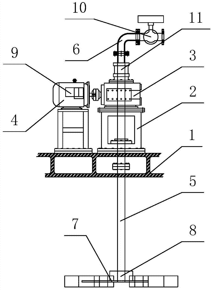
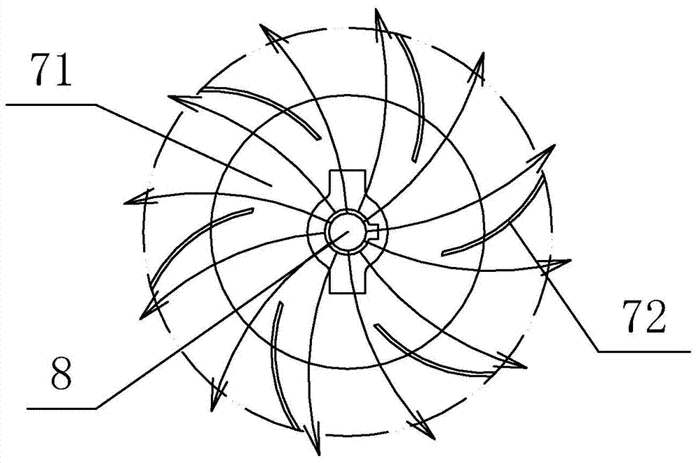
[0014] Embodiment 1: as figure 1 and figure 2 As shown, the present invention comprises frame 1 and support 2, and described support 2 is fixed on the frame 1, and described frame 1 is fixedly installed with reducer 3, and the input end of described reducer 3 is connected with motor 4. The output end is connected with a stirring shaft 5, the stirring shaft 5 is hollow inside, the upper end of the stirring shaft 5 is connected with the air inlet pipe 6 through a rotary sealing joint 11, and a disc turbine type curved blade stirrer 7 is provided at the lower end, so The disc turbine type curved blade agitator 7 includes a stirring disc 71 and a stirring curved blade 72, the stirring curved blades 72 are evenly distributed on the stirring disc 71, the bottom end of the stirring shaft 5 is located at the center of the stirring disc 71, and Have ventilated aeration hole 8.
Embodiment 2
[0015] Embodiment 2: Same as the above embodiment 1, wherein the motor 4 is connected with a frequency converter 9 , and the air inlet of the air inlet pipe 6 is provided with an aeration rate regulating valve 10 .
[0016] In the mixing process of the present invention, the gas is charged into the air intake pipe 6 by connecting the external air source at the air inlet of the air intake pipe 6, the aeration rate is controlled by the aeration rate regulating valve 10, the motor 4 works, and the reducer 3 is driven to work , so that the stirring shaft 5 rotates, and after the stirring shaft 5 is hollow, it communicates with the air inlet pipe 6 through the rotary sealing joint 11, the gas passes from the stirring shaft 5 into the liquid surface, overflows from the aeration hole 8, and the overflowing gas is moving upward At this time, it is blocked by the stirring disk 71, thereby turning to overflow to the side of the stirring disk 71. At this time, the gas overflowing sideways...
PUM
 Abstract
Description
Claims
Application Information
 - R&D Engineer
- R&D Manager
- IP Professional
- Industry Leading Data Capabilities
- Powerful AI technology
- Patent DNA Extraction
Browse by: Latest US Patents, China's latest patents, Technical Efficacy Thesaurus, Application Domain, Technology Topic, Popular Technical Reports.
© 2024 PatSnap. All rights reserved.Legal|Privacy policy|Modern Slavery Act Transparency Statement|Sitemap|About US| Contact US: help@patsnap.com