Fancy yarn device

A technology of fancy yarn and core yarn, which is applied in the field of spinning, can solve problems such as the restriction of rotation speed, low quality of covered yarn, and limited length of covered yarn, so as to improve work efficiency, lower load-carrying weight and avoid multi-nodes Effect

Active Publication Date: 2015-07-15
DONGHUA UNIV +1
View PDF7 Cites 3 Cited by
  • Summary
  • Abstract
  • Description
  • Claims
  • Application Information

AI Technical Summary

Problems solved by technology

[0004] In such a wrapping method, since the hollow spindle 5 needs to drive the double-sided bobbin 7 to rotate, the load is relatively large, the energy consumption is relatively high, and its rotation speed is restricted to a certain extent.
Moreover, before the covering action, the outsourcing yarn needs to be wound onto the double-sided bobbin dedicated to the hollow spindle spinning machine through the winding machine. After winding, the outsourcing yarn bobbin has less yarn, and it needs to be knotted to form knots after each replacement. Resulting in low quality of covered yarn
In addition, in the traditional covering method, the length of the covering yarn is limited. To complete a package of covering yarn, it may be necessary to replace multiple covering yarn packages, making it difficult to achieve continuous covering production

Method used


Image

  • Fancy yarn device
  • Fancy yarn device
  • Fancy yarn device

Examples


Embodiment 1

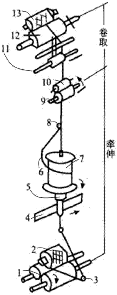
[0036] Embodiment 1: as figure 2 As shown, a mechanical fancy yarn device includes the following structure:

[0037] The suspending body 2 is suspended above the suspending support body 1 without being in contact with the suspending support body 1, and its function is to allow the outer covering yarn to rotate freely without interference. The suspending body 2 and the suspending support body 1 are suspended in the form of electromagnetic levitation, and its internal structure and specific driving principle are consistent with those in the prior art, so they are not shown in the figure. The suspension 2 is used to support the core yarn reel 3 , and the core yarn reel 3 is placed on the suspension 2 during use, so that the core yarn 10 can be drawn out from above the suspension 2 .

[0038] Mounting frame 4, the suspension body 2 is provided with a mounting frame 4, and a tensioner 5 is installed on the mounting frame 4, so that the core yarn 10 output by the core yarn drum 3 ...

Embodiment 2

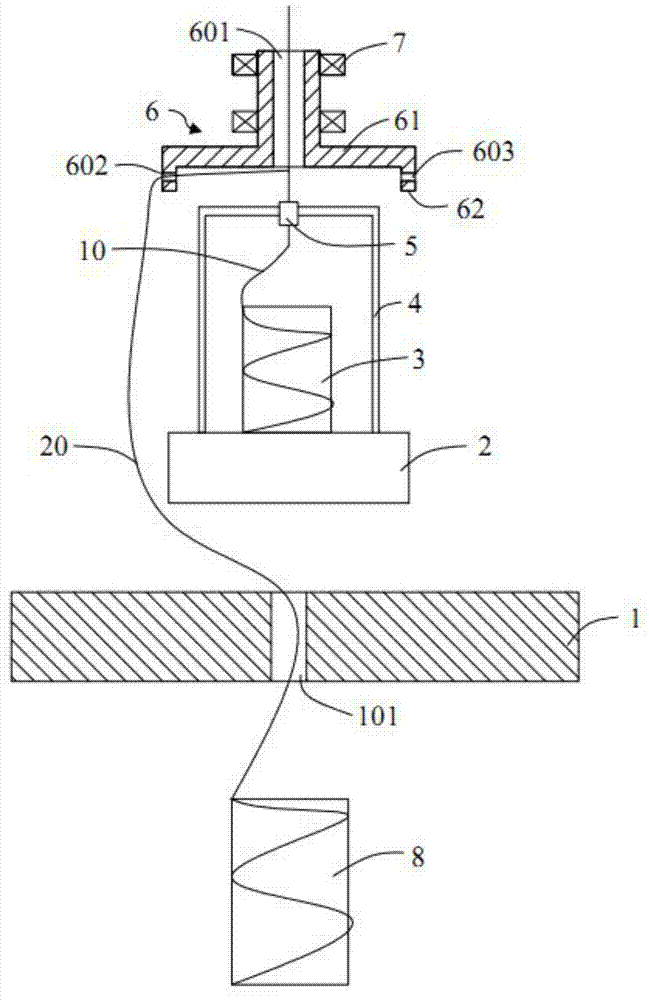
[0050] Embodiment 2: As another suspension method, the suspension support body 1 is located above the suspension body 2 to make it in a suspended state, the installation frame 4 is fixed on the bottom of the suspension body 2, and is U-shaped, and the core yarn reel 3 is placed on the installation In the inner space of frame 4.

[0051] If the position of the outer yarn reel 8 is still arranged at the bottom, then as Figure 4 As shown, holes are opened on the suspension body 2 to facilitate the output of the core yarn from the core yarn reel 3, and the outer covering yarn released from the outer covering yarn reel 8 passes through the guide wire hole of the rotating part 6, and the rotation of the rotating part 6 drives it in the rotating part. The core yarn is covered in the space between 6 and the suspension 2, and the fancy yarn is output from the center hole. In order to ensure that the outer covering yarn can bypass the core yarn reel 3, the mounting frame 4 and the flo...

Embodiment 3

[0054] Embodiment 3: The rotating part 6 can not only be arranged directly above the suspension body 2 and its core yarn reel 3 as shown in Embodiment 1, but also can be arranged directly below the suspension body 2 and its core yarn reel 3 .

[0055] like Figure 7 As shown, the longitudinal section of the main body of the rotating part 6 under the suspension 2 is T-shaped, and the ring-shaped protrusion is fixed on the upper part of the main body to form a whole. The yarn rotates on the outer circumference of the mounting frame 4 through the central hole and the guide wire hole of the rotating part 6, and the output core yarn is wrapped on the mounting frame 4 and then wound into a tube.

[0056] exist Figure 7 On the basis of the situation, the outsourcing yarn reel 8 can be placed on the top of the mounting frame 4, such as Figure 8 As shown, the covering yarn covers the core yarn in the space between the suspension body 2 and the rotating component 6 through the guide...


PUM


Abstract

The invention discloses a fancy yarn device. The fancy yarn device comprises a support component, a winding mechanism, a core yarn drum, a covering yarn drum, a suspension body, a suspension body support body for controlling the spatial position of the suspension body, and a rotating component, wherein a mounting frame and the core yarn drum are arranged on the suspension body; the rotating component is arranged on the support component. The core yarn drum is suspended through the suspension body, so that a space is formed around the core yarn drum to wrap core yarns with covering yarns, and the rotating component only needs to drive a single covering yarn to rotate during covering, so that the whole covering yarn drum does not need to be driven. By adopting the way, the load capacity of the rotating component is low, so that high-speed rotation can be realized conveniently, and the working efficiency is increased.

Description

technical field [0001] The invention belongs to the technical field of spinning, in particular, the invention relates to a fancy yarn device. Background technique [0002] Covered yarn is a kind of fancy yarn, which is divided into mechanical covering and air covering. The air-covered yarn is a yarn in which the outsourcing fiber filaments and spandex yarns are drafted through a certain type of nozzle at the same time, and the rhythmic network points are formed by the regular spray pressure of high-compression air. Mechanical covering is to continuously rotate and wrap the outer fiber filaments on the core yarn that is drafted at a constant speed. The mechanical covering yarn has a certain twist after being twisted. The core yarn is generally an elastic yarn, and the covering yarn combines the advantages of the core yarn and the outer covering yarn to make up for the defects of the single component filament. [0003] The commonly used covering yarn machine used nowadays is...

Claims


Application Information

Patent Timeline
IPC IPC(8): D02G3/34D02G3/36D01H7/88
Inventor 杨崇倡邹鲲张荣根王永兴王生泽缪小方
Owner DONGHUA UNIV
Why Eureka
Try Eureka