A fancy yarn device
A fancy yarn and core yarn technology, applied in the field of spinning, can solve the problems of limited rotation speed, low quality of covered yarn, high energy consumption, etc., and achieve the effects of improving work efficiency, avoiding multi-nodes, and low load-carrying weight
- Summary
- Abstract
- Description
- Claims
- Application Information
AI Technical Summary
Problems solved by technology
Method used
Image
Examples
Embodiment 1
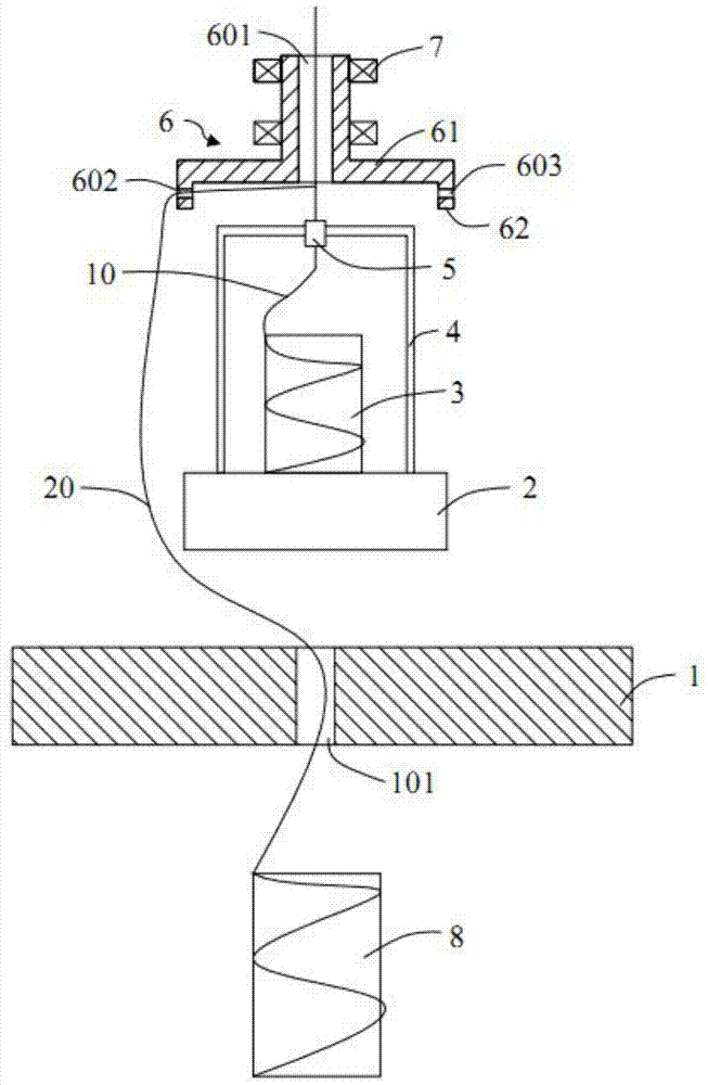
[0036] Embodiment 1: as figure 2 As shown, a mechanical fancy yarn device includes the following structure:
[0037] The suspending body 2 is suspended above the suspending support body 1 without being in contact with the suspending support body 1, and its function is to allow the outer covering yarn to rotate freely without interference. The suspending body 2 and the suspending support body 1 are suspended in the form of electromagnetic levitation, and its internal structure and specific driving principle are consistent with those in the prior art, so they are not shown in the figure. The suspension 2 is used to support the core yarn reel 3 , and the core yarn reel 3 is placed on the suspension 2 during use, so that the core yarn 10 can be drawn out from above the suspension 2 .
[0038] Mounting frame 4, the suspension body 2 is provided with a mounting frame 4, and a tensioner 5 is installed on the mounting frame 4, so that the core yarn 10 output by the core yarn drum 3 ...
Embodiment 2
[0050] Embodiment 2: As another suspension method, the suspension support body 1 is located above the suspension body 2 to make it in a suspended state, the installation frame 4 is fixed on the bottom of the suspension body 2, and is U-shaped, and the core yarn reel 3 is placed on the installation In the inner space of frame 4.
[0051] If the position of the outer yarn reel 8 is still arranged at the bottom, then as Figure 4 As shown, holes are opened on the suspension body 2 to facilitate the output of the core yarn from the core yarn reel 3, and the outer covering yarn released from the outer covering yarn reel 8 passes through the guide wire hole of the rotating part 6, and the rotation of the rotating part 6 drives it in the rotating part. The core yarn is covered in the space between 6 and the suspension 2, and the fancy yarn is output from the center hole. In order to ensure that the outer covering yarn can bypass the core yarn reel 3, the mounting frame 4 and the flo...
Embodiment 3
[0054] Embodiment 3: The rotating part 6 can not only be arranged directly above the suspension body 2 and its core yarn reel 3 as shown in Embodiment 1, but also can be arranged directly below the suspension body 2 and its core yarn reel 3 .
[0055] Such as Figure 7 As shown, the longitudinal section of the main body of the rotating part 6 under the suspension 2 is T-shaped, and the ring-shaped protrusion is fixed on the upper part of the main body to form a whole. The yarn rotates on the outer circumference of the mounting frame 4 through the central hole and the guide wire hole of the rotating part 6, and the output core yarn is wrapped on the mounting frame 4 and then wound into a tube.
[0056] exist Figure 7 On the basis of the situation, the outsourcing yarn reel 8 can be placed on the top of the mounting frame 4, such as Figure 8 As shown, the covering yarn covers the core yarn in the space between the suspension body 2 and the rotating component 6 through the gu...
PUM
 Abstract
Description
Claims
Application Information
 - R&D
- Intellectual Property
- Life Sciences
- Materials
- Tech Scout
- Unparalleled Data Quality
- Higher Quality Content
- 60% Fewer Hallucinations
Browse by: Latest US Patents, China's latest patents, Technical Efficacy Thesaurus, Application Domain, Technology Topic, Popular Technical Reports.
© 2025 PatSnap. All rights reserved.Legal|Privacy policy|Modern Slavery Act Transparency Statement|Sitemap|About US| Contact US: help@patsnap.com


