
dryer or pyrolyzer

A technology of pyrolyzer and dryer, which is applied in the direction of drying solid materials, drying gas arrangement, non-progressive dryer, etc., and can solve the problem of limiting the operating capacity of the device, the structure of the rotating material bed and the load-bearing limit, and the buckling of the support structure To avoid problems such as collapse, to achieve the effects of not being easy to buckle and collapse, increasing the bearing weight, and enhancing fluidity

Active Publication Date: 2016-11-30
CHNA ENERGY INVESTMENT CORP LTD +1
View PDF4 Cites 0 Cited by
  • Summary
  • Abstract
  • Description
  • Claims
  • Application Information

AI Technical Summary

Problems solved by technology

However, because the design diameter of the feeding pipe and its support and driving bearing is too small compared to the rotating material bed, this device is only suitable for occasions where the diameter of the rotating material bed is small and the material handling capacity is not much, in other words, for the rotating material bed The structure and load bearing have strict restrictions
If the mass of the rotating material bed is too large, it will cause buckling and collapse of the entire supporting structure (bearings and feeding tubes), thus severely limiting the scale-up of the device and the operating capacity of the device

Method used


Image

  • dryer or pyrolyzer
  • dryer or pyrolyzer
  • dryer or pyrolyzer

Examples


Embodiment Construction

[0030] Specific embodiments of the present invention will be described in detail below in conjunction with the accompanying drawings. It should be understood that the specific embodiments described here are only used to illustrate and explain the present invention, and are not intended to limit the present invention.

[0031] In the present invention, unless stated otherwise, the used orientation words such as "up and down" are usually for the direction shown in the drawings or for the vertical, vertical or gravity direction The terms used to describe the mutual positional relationship of each component; similarly, for the convenience of understanding and description, "left and right" usually refer to the left and right shown in the drawings; Inside and outside, but the above-mentioned orientation words are not used to limit the present invention.

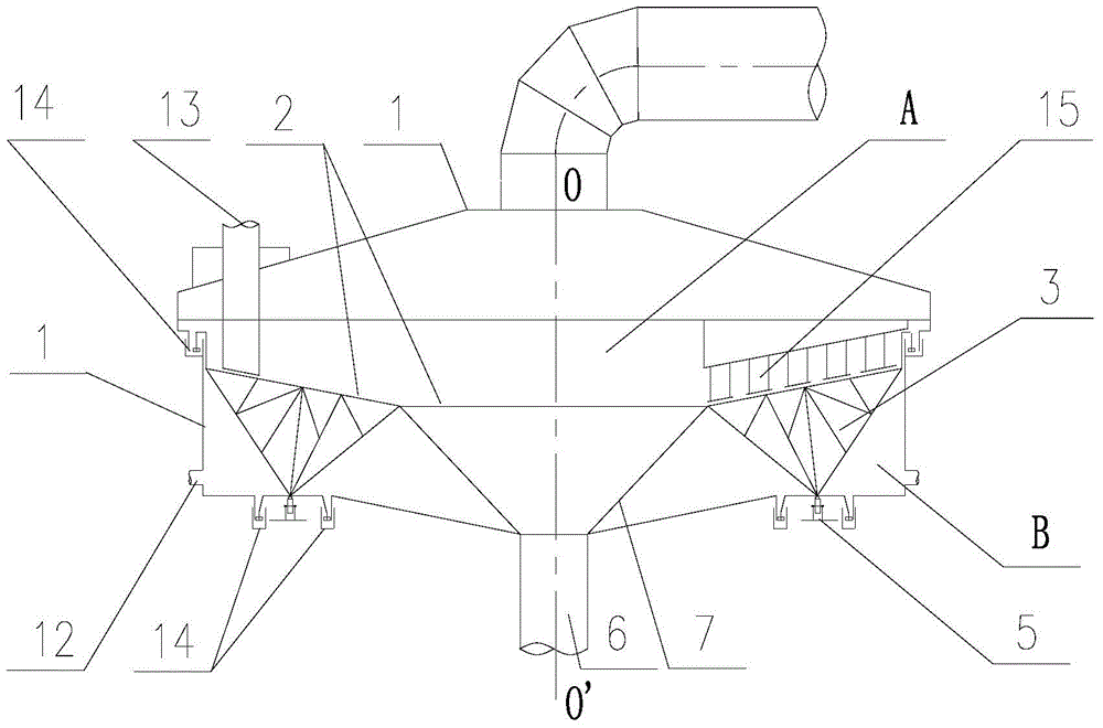
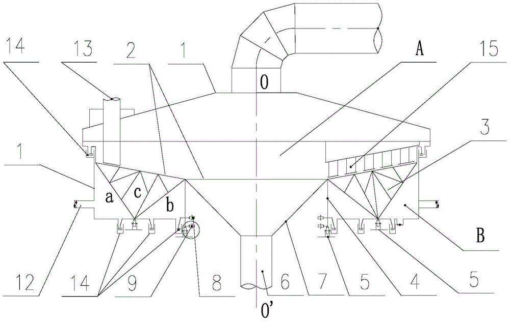
[0032] like figure 1 In one embodiment shown, the present invention firstly provides a dryer or a pyrolyzer, which can be used ...


PUM


Abstract

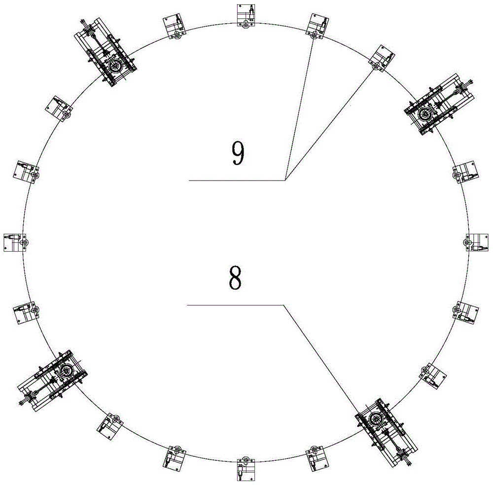
The present invention discloses a drier or pyrolyzer, which comprises a shell (1), a rotating material bed (2) and a truss support (3). On the basis of the truss support, the Cylindrical support (4) is added, the top of the cylindrical support is supported on the central area of ​​the bottom surface of the rotating material bed, the truss support is connected and supported on the outer ring area surrounding the central area on the bottom surface of the rotating material bed, the bottom end of the truss support is connected to the The bottom ends of the cylindrical supports are spaced along the radial direction of the rotary material bed, and are respectively rotatably supported on the bottom platform structure (5) to jointly support the rotation of the rotary material bed along its rotation axis (OO'). Wherein, the bottom end of the truss support is located between the feeding pipe (13) and the feeding hole (21) in the radial direction of the rotating material bed. The bottom of the rotating material bed has two rotatable support points at intervals, which greatly increases the rotation stability, improves the load-bearing weight of the material, and makes the rotating material bed less prone to buckling and collapse. In addition, the fluidity of the material in the gap between the guide plate and the rotating material bed can be effectively enhanced.

Description

technical field [0001] The invention relates to a drier or a pyrolyzer, in particular to a drier or a pyrolyzer with a large material handling capacity. Background technique [0002] Lignite storage in my country is very rich, accounting for about 40% of my country's coal storage, mainly distributed in Yunnan, Inner Mongolia, Northeast China, Sichuan and other provinces. Lignite is characterized by high water content, generally accounting for 20-60% of the proportion; low calorific value, about 2500-4500 kcal / kg; high volatile content, about 40-50% (dry ash-free basis). This type of coal has low market value, high transportation costs, low power generation efficiency and difficult gasification technology. The market value of this kind of coal is far lower than that of high-quality coal. Using the gas heat carrier process to pyrolyze lignite can extract pyrolysis oil from it and process it into high-quality oil products, extract hydrogen-rich gas for oil quality improvement,...

Claims


Application Information

Patent Timeline
Patent Type & Authority Patents(China)
IPC IPC(8): F26B11/10F26B21/00F26B25/04C10B49/04C10B53/04
Inventor 李君郭强卢洪郭屹
Owner CHNA ENERGY INVESTMENT CORP LTD
Learn More