
Counterweight assembly, counterweight mechanism using the counterweight assembly, and pan/tilt

A technology of pan/tilt and components, which is applied in the direction of the machine platform/support, camera body, camera, etc., which can solve the problems of inconvenient adjustment, difficulty in accurately adjusting the relative position, heavy weight, etc., and achieves a wide range of applications and a simple adjustment process Labor-saving effect

Inactive Publication Date: 2017-04-19
SZ DJI OSMO TECH CO LTD
View PDF12 Cites 0 Cited by
  • Summary
  • Abstract
  • Description
  • Claims
  • Application Information

AI Technical Summary

Problems solved by technology

However, the above-mentioned adjustable pan / tilt relies on the photographer to manually adjust the center of gravity of the electronic device, and it is difficult to accurately adjust the relative position of the carrier platform and the installation platform
When the overall weight of the electronic device is heavy and the weight distribution is uneven, due to the limited range of relative position change between the bearing platform and the installation platform, the limitation of the adjustment stroke makes it difficult for the electronic device to maintain a balanced state within the adjustable range. The center of gravity of the device is offset, and its gravity will cause the torque to be applied between the rotating shafts of the gimbal, which will affect the service life of the gimbal
In addition, because the carrying platform is used to carry the electronic device, it carries a relatively heavy weight, so that when the photographer adjusts the position of the carrying platform relative to the installation platform, the operation is laborious and inconvenient.

Method used


Image

  • Counterweight assembly, counterweight mechanism using the counterweight assembly, and pan/tilt
  • Counterweight assembly, counterweight mechanism using the counterweight assembly, and pan/tilt
  • Counterweight assembly, counterweight mechanism using the counterweight assembly, and pan/tilt

Examples


Embodiment Construction

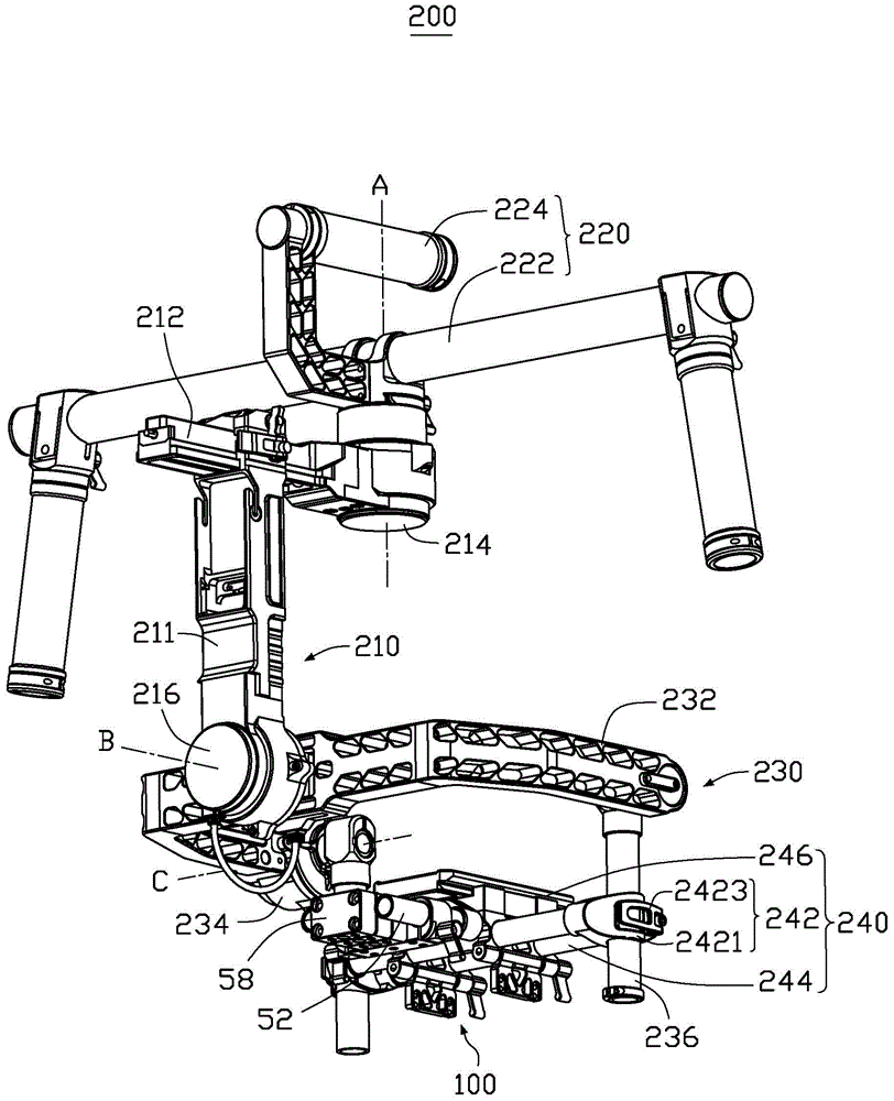
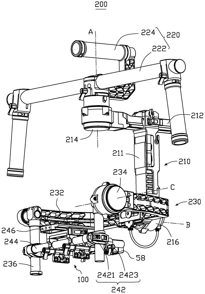
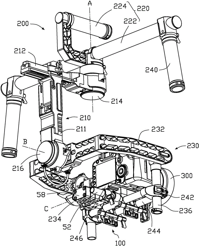
[0020] see Figure 1 to Figure 4 , the pan-tilt 200 according to the embodiment of the present invention is used for installing electronic devices 300 such as video cameras and cameras.

[0021] In this embodiment, the gimbal 200 is a three-axis gimbal. The cloud platform 200 includes a support body 210, a first support assembly 220 and a second support assembly 230 installed at both ends of the support body 210, a third support assembly 240 installed on the second support assembly 230, and a third support assembly installed on the third support assembly. The counterweight mechanism 100 on the support assembly 240 .

[0022] The supporting body 210 includes a fixing part 211 , a translation part 212 , a first driving part 214 and a second driving part 216 .

[0023] The fixing part 211 is substantially columnar, and the translation part 212 is disposed substantially vertically on one end of the fixing part 211 , and the translation part 212 can translate along a direction su...


PUM


Abstract

The invention relates to a counterweight component, a counterweight mechanism using the counterweight component, and a cloud platform. The cloud platform includes a supporting body and a bearing platform connected to the supporting body. The platform also includes a mounting rod connected to the supporting body and a counterweight component adjustably disposed on the mounting rod. The bearing platform is connected to the supporting body. On the mounting rod, the counterweight assembly includes a connecting seat connected to the bearing platform, a guide member provided on the connecting seat, a support member movably set on the guide member, and a support member connected to the support member. A counterweight block and a connecting piece provided on the counterweight block. A fixed part is formed on the connecting seat. The guide piece is provided on the fixed part. The counterweight block is connected to the support member through the connecting piece. , the counterweight block can move along the guide member driven by the support member to adjust the center of gravity of the platform and the counterweight assembly.

Description

technical field [0001] The invention relates to a counterweight assembly, a counterweight mechanism using the counterweight assembly and a cloud platform. Background technique [0002] In the process of using electronic devices such as video cameras and cameras to shoot with electric pan / tilts, according to different shooting requirements, it is often necessary to use electronic devices equipped with telephoto lenses for shooting. Due to the heavy weight of the telephoto lens itself, when it is mounted on a light electronic device, the center of gravity of the electronic device will be unstable, and it is easy to shake on the gimbal, affecting the shooting quality. In order to solve the above problems, the existing cloud platform has a bearing platform for installing the electronic device and a mounting platform connected to the bearing platform. The bearing platform can be adjusted to move relative to the mounting platform, so that the photographer can The relative positio...

Claims


Application Information

Patent Timeline
Patent Type & Authority Patents(China)
IPC IPC(8): F16F15/28F16M11/04G03B17/56
CPCF16F15/28F16M11/04G03B17/56F16M11/041F16M11/045F16M11/18F16M11/205F16M13/04F16M2200/044G03B17/561G03B17/563G02B7/001
Inventor 潘立忠赵岩崇
Owner SZ DJI OSMO TECH CO LTD
Learn More