EEG collection device

An EEG signal and acquisition device technology, applied in medical science, sensors, diagnostic recording/measurement, etc., can solve problems such as troublesome operation, patient scalp damage, time-consuming and labor-intensive, etc., and achieve the effect of increasing friction.

Active Publication Date: 2015-07-22
HENAN RYAN MEDICAL INSTR
View PDF7 Cites 7 Cited by
  • Summary
  • Abstract
  • Description
  • Claims
  • Application Information

AI Technical Summary

Problems solved by technology

[0003] At present, EEG signal acquisition electrodes can be divided into three types: the first type is columnar electrodes, which are large-volume columnar electrodes, and each columnar electrode is inserted into the mesh electrode cap one by one. The barrier makes it difficult for the electrodes to be close to the scalp, which affects the inspection effect. The columnar click is bulky, and it is easy to fall from the mesh electrode cap when the head is shaken. It is not suitable for long-term brain examinations.
The disadvantage is that the paste process needs to be peeled off the hair one by one, which is time-consuming and labor-intensive. The electrode paste

Method used


Image

  • EEG collection device
  • EEG collection device
  • EEG collection device

Examples


Embodiment 1

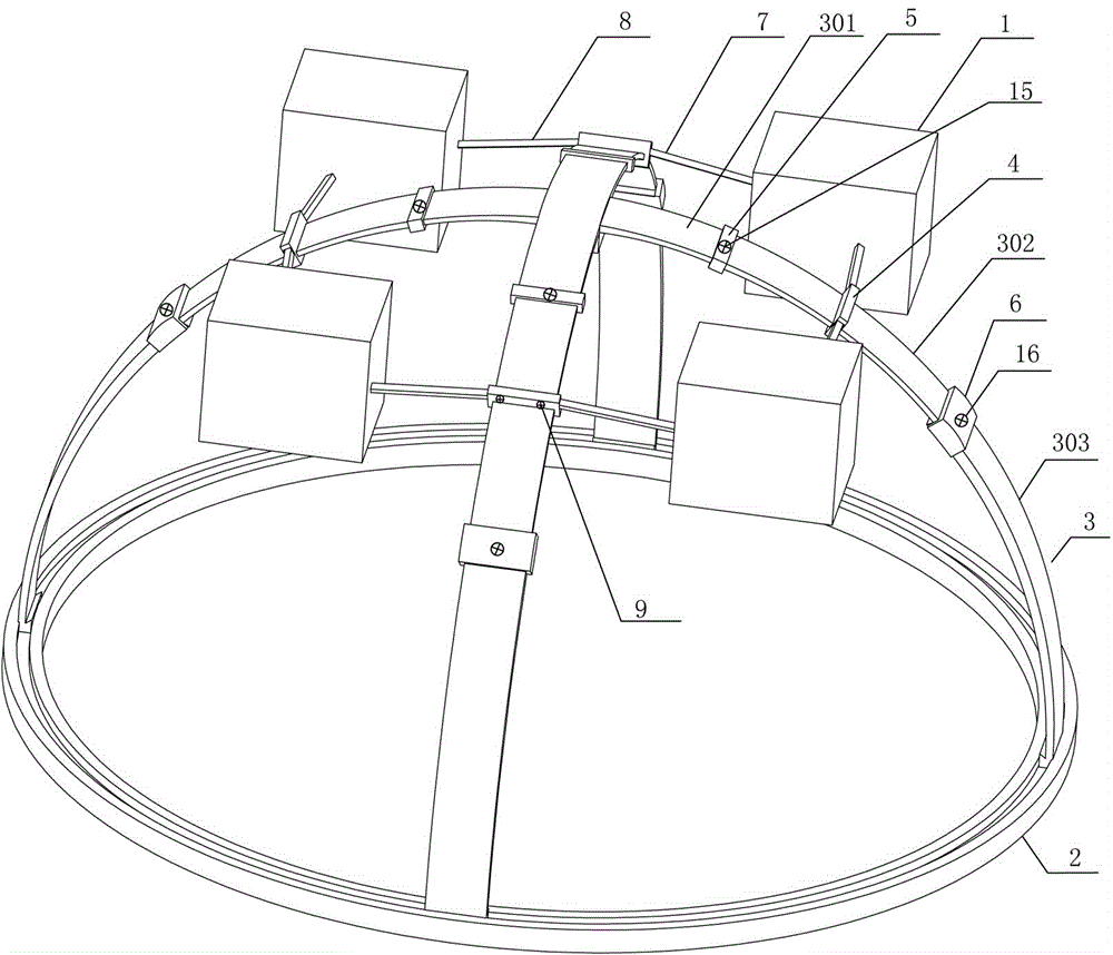
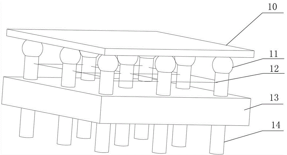
[0032] Such as figure 1 , image 3 As shown, it includes an electroencephalogram signal collection electrode 1 and an electrode holder for fixing the electroencephalogram signal collection electrode. The extrusion plate 10 above the needle group and the power source that drives the extrusion plate to reciprocate. The power source in this embodiment is an electric push rod (not shown) fixed on the fixed plate above the extrusion plate. The push rod of the push rod is connected with the extrusion plate 10 . The pin group includes a plurality of pins, and each pin includes a conductive pin body 14 with a through hole in the center and a plug for extruding and inhaling the conductive gel from the through hole, which is arranged on the upper part of the conductive pin body 14 and communicated with the through hole. The operating mechanism, in this embodiment, the operating mechanism is a hollow body 11 made of elastic material, and the lower port of the hollow body 11 communicate...

Embodiment 2

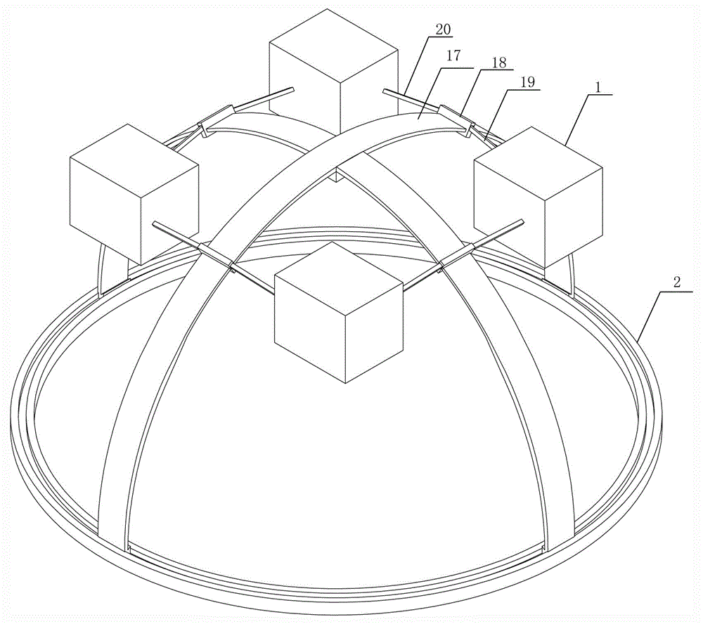
[0035] Different from Example 1, as figure 2 As shown, the fixed arc plate includes an arc plate body 17 and a fixing piece 18 arranged on the arc plate body 17, the elastic mounting plate is fixed on the fixing piece or is integrated with the fixing piece, and the elastic mounting plate and the corresponding fixed arc plate Vertically arranged and extending obliquely downward to both sides, the elastic mounting plate includes a left elastic mounting plate 19 and a right elastic mounting plate 20 . The EEG signal acquisition device with this structure cannot adjust the length of the arc plate body and the length of the elastic mounting plate, and can only collect EEG signals from people with similar head shapes and sizes. Except that the length of the arc plate body and the length of the elastic mounting plate cannot be adjusted, it has all the other advantages of the EEG signal acquisition device in Embodiment 1.

[0036] In other embodiments of the present invention, diffe...


PUM

PropertyMeasurementUnit
Lengthaaaaaaaaaa

Abstract

The invention provides an EEG collection device which comprises an EEG collection electrode and an electrode fixing frame used for fixing the EEG collection electrode. The EEG collection electrode comprises a fixing plate, a thrusting needle set, a squeezing plate and a power source. The electrode fixing frame comprises a head loop and four fixing arc plates. Each fixing arc plate is provided with an elastic installation plate. The elastic installation plates are perpendicular to the corresponding fixing arc plates and extend downwards and obliquely. The outer ends of the elastic installation plates of the adjacent fixing arc plates are fixed to the same fixing plate. According to the EEG collection device, conductive needles are pressed on the scalp by penetrating through hair under the elastic effect of the elastic installation plates, and therefore the poor contact phenomenon is avoided. Through the cooperative effect of the EEG collection electrode and the electrode fixing frame, EEG can be stably and accurately detected, the requirement for a detector is greatly lowered, and the detector even can freely move.

Description

technical field [0001] The invention relates to a medical device, in particular to an electroencephalogram signal acquisition device. Background technique [0002] EEG measurement is a common medical diagnosis method, and physiological and pathological information can be obtained by collecting EEG signals. EEG measurements can also provide an important source of EEG signals for emerging wearable devices. EEG measurement is to place electrodes at a certain position on the head to accurately acquire weak EEG signals, and collect, amplify, process and record the EEG signals through EEG equipment such as EEG. [0003] At present, the EEG signal acquisition electrodes can be divided into three types: the first is columnar electrodes, which are large-volume columnar electrodes, and each columnar electrode is inserted into the mesh electrode cap one by one. The barrier makes it difficult for the electrodes to be closely attached to the scalp, which affects the inspection effect. ...

Claims


Application Information

Patent Timeline
IPC IPC(8): A61B5/0476
CPCA61B5/6803A61B5/291A61B5/369
Inventor 吴建春杨波易怀广王明秋
Owner HENAN RYAN MEDICAL INSTR
Why Eureka
Try Eureka