Pedicle screw and bar pressing device

A technology of pedicle screw and pressing rod, which is used in medical science, surgery, fixator and other directions, can solve the problem that it is easy to get stuck in the groove of the side wall of the screw seat, and it needs to be repeatedly shaken from side to side to take it out, with high cost and low efficiency. and other problems, to achieve the effect of convenient direction and jacking degree, precise position control, and convenient use

Active Publication Date: 2015-07-22
SHANDONG WEIGAO ORTHOPEDIC DEVICE COMPANY
View PDF8 Cites 15 Cited by
  • Summary
  • Abstract
  • Description
  • Claims
  • Application Information

AI Technical Summary

Problems solved by technology

In actual use, there are the following disadvantages: 1. The tail of the screw is long, not only the processing is complicated and the cost is high, but also an additional breaking operation needs to be performed when the operation is completed; 2. After the operation is completed, the nut needs to be unscrewed from the bottom of the extension sleeve. Due to the large number of screws and sleeves used in orthopedic surgery, doctors need to spend a lot of time taking out the nuts one by one, which is very time-consuming, which not only prolongs the operation time, but also increases the risk of bleeding and infection for t

Method used


Image

  • Pedicle screw and bar pressing device
  • Pedicle screw and bar pressing device
  • Pedicle screw and bar pressing device

Examples


Embodiment Construction

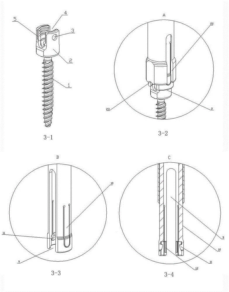
[0021] Such as image 3 The pedicle screw shown in Figure 3-1 includes a screw body 1 and a screw seat 2. The screw seat 2 is provided with a U-shaped rod placement groove 3, and the U-shaped rod placement groove 3 divides the screw seat into mutually symmetrical cross sections. Arc-shaped left plate body and right plate body, positioning grooves 4 are respectively provided on the left side of the left plate body and the right side of the right plate body, and the front side and the rear side of the upper end of the left plate body and the right plate body are respectively longitudinally provided with There is a positioning chute 5 with an open upper end. It can be seen from the figure that the front and rear sides of the screw seat are processed into flat surfaces, and the positioning chute 5 is arranged on the flat surfaces of the upper ends of the left plate body and the right plate body.

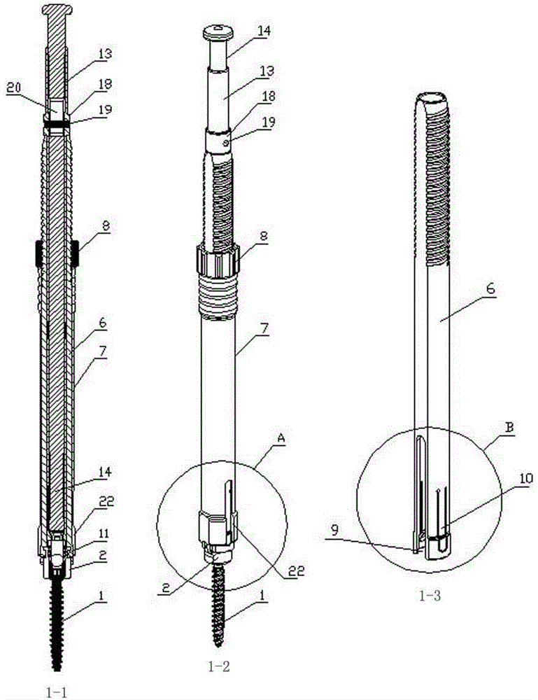
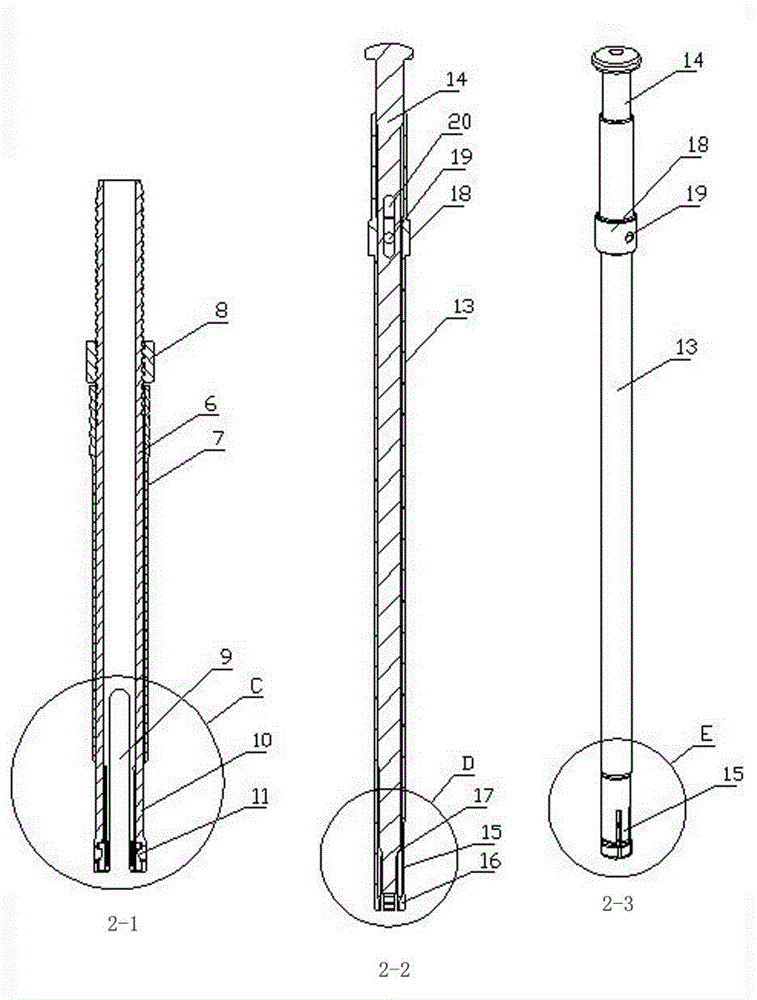
[0022] Such as figure 1 , figure 2 , image 3 Middle 3-2, 3-3, 3-4, Figure 4T...


PUM


Abstract

The invention provides a pedicle screw and a bar pressing device. The pedicle screw comprises a screw body and a screw base. A U-shaped bar containing groove divides the screw base into a left board body and a right board body. Positioning grooves are formed in the left side of the left board body and the right side of the right board body respectively. The pedicle screw is characterized in that positioning chutes with the upper open ends are longitudinally formed in the front sides and the rear sides of the upper ends of the left board body and the right board body respectively. The bar pressing device comprises an extension sleeve, a bar pressing sleeve and a bar pressing nut. A bar pressing groove is formed in the lower portion of the extension sleeve. Two opposite strip openings are formed in the side wall of the extension sleeve. Positioning elastic pieces are arranged in the strip openings. Positioning protrusions are arranged on the inner sides of the lower ends of the two positioning elastic pieces. Positioning sliding blocks matched with the positioning chutes and protruding inwards are arranged on the inner wall of the extension sleeve, the extension sleeve is sleeved with the bar pressing sleeve, and the bar pressing nut is arranged at the upper portion, above the bar pressing sleeve, of the extension sleeve. The pedicle screw and the bar pressing device have the advantages that connection is easy, convenient and quick, connection reliability is high, disengagement is not likely to happen, detachment is easy, the bar pressing operation speed is high, and efficiency is high.

Description

technical field [0001] The invention relates to the technical field of medical instruments for spinal surgery, in detail, it is a pedicle with simple and quick connection, high connection reliability, not easy to loose, easy to disassemble, fast operation speed and high efficiency when used in conjunction with each other Screw and bar device. Background technique [0002] We know that compression rod is an intraoperative operation that is often required in spinal orthopedic and posterior spinal minimally invasive surgery. The method is to press the connecting rod into the U-shaped groove of the screw through a tool or a long-tailed pedicle screw. For multi-segment posterior thoracolumbar surgery, when the pedicle screw is implanted into the patient's vertebral body, the position of the screw seat of the pedicle screw cannot be in a straight line in most cases, nor can it be completely fitted and fixed. The axis of the rod, after putting the connecting rod into the nail seat...

Claims


Application Information

Patent Timeline
IPC IPC(8): A61B17/70A61B17/86A61B17/92
CPCA61B17/00234A61B17/70A61B17/7076A61B17/8615A61B17/863A61B17/8635A61B17/8685A61B17/92A61B2017/564A61B2017/8655A61B2017/922
Inventor 寇万福邬春晖邹海波王晗于朝亮高亚军
Owner SHANDONG WEIGAO ORTHOPEDIC DEVICE COMPANY
Why Eureka
Try Eureka