Double-layer solid parking equipment

A three-dimensional parking and double-deck technology, which is applied to the buildings, building types, buildings, etc. where cars are parked, can solve the problems of the upper car-carrying plate inclination, low translation efficiency, and high ground requirements, and achieve simple ground construction and stable and reliable operation. , the effect of low ground requirements

Active Publication Date: 2015-07-22
湖南有位智能科技有限公司
View PDF8 Cites 4 Cited by
  • Summary
  • Abstract
  • Description
  • Claims
  • Application Information

AI Technical Summary

Problems solved by technology

However, because the lower parking mechanism adopts the form of slide rails, the translation efficiency is low, and when the rails are fixed on the ground, the ground requirements are high, and the ground of the entire parking garage area needs to be treated, which is costly;
[0006] At the same time, since the rotation fulcrums of the active arm and the movable arm are on the same horizontal plane, in order to avoid interference with the lower vehicle during the rotation of the upper vehicle loading plate, the hydraulic cylinder piston needs to be extended first, and then the hydraulic cylinder piston should be shortened. In this process, if the telescopic cooperation between the active arm and the driven arm is not in place, the upper vehicle-carrying plate will tilt, causing the vehicle to slide down and be damaged; even for automatic control, it is necessary to design a set of high-reliability procedures, which is time-consuming Laborious and costly

Method used


Image

  • Double-layer solid parking equipment
  • Double-layer solid parking equipment
  • Double-layer solid parking equipment

Examples


Embodiment Construction

[0060] For the convenience of description, the description of the relative positional relationship of each component (such as: front, rear, left, right, etc.) is described according to the layout direction of the drawings in the specification.

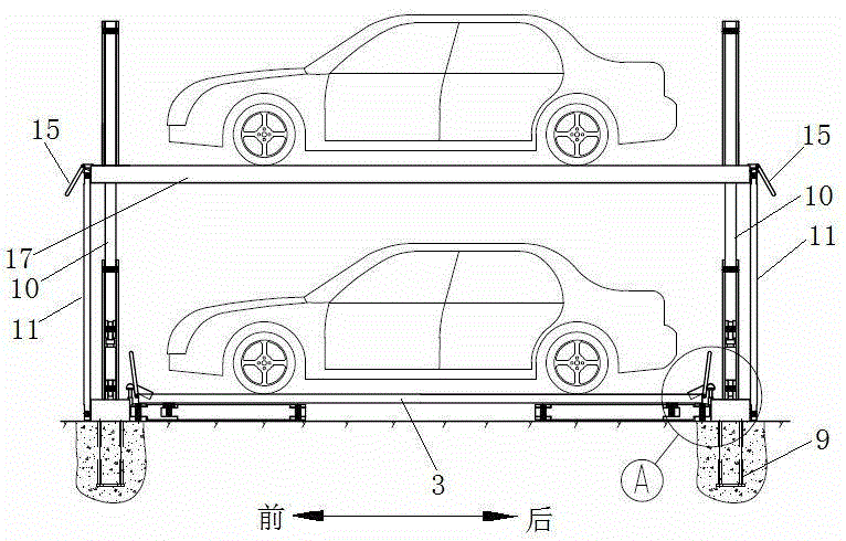
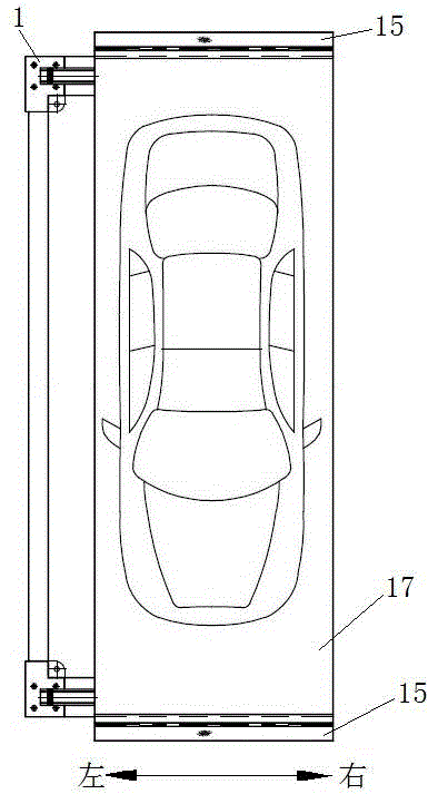
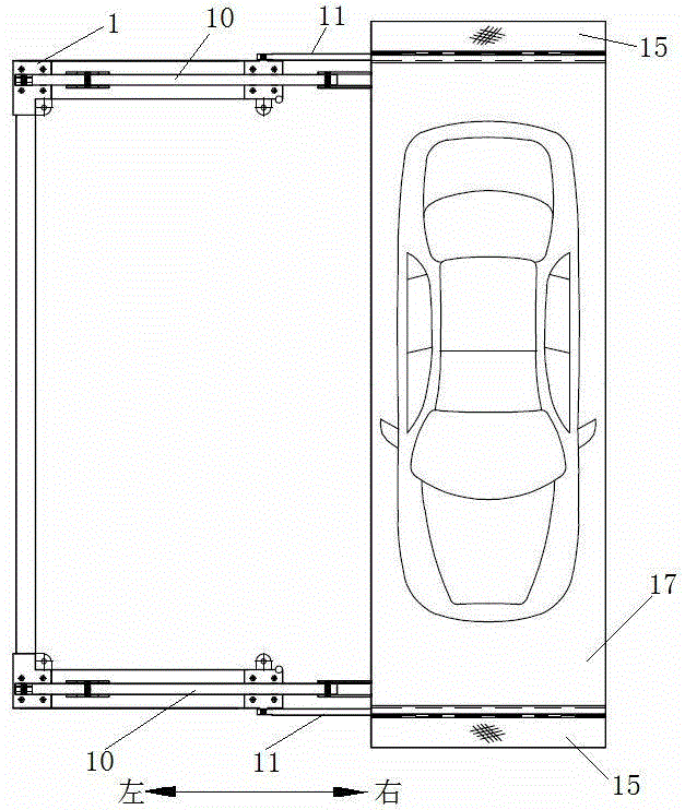
[0061] like Figure 1-14 As shown, a double-layer three-dimensional parking device includes a lower parking mechanism and an upper parking mechanism directly above it. The upper parking mechanism can rotate around the lower parking mechanism and move in translation to the side of the same horizontal plane as the lower parking mechanism. , the upper parking mechanism includes an upper vehicle frame, a driving arm 10 respectively arranged at the front and rear ends of the upper vehicle frame, a driven arm 11 respectively arranged at the front and rear ends of the upper vehicle frame, and a rotary drive;

[0062] The upper end of the driven arm 11 is hinged with the upper floor bearing frame, the lower end of the driven arm 11 is hinged w...


PUM


Abstract

The invention discloses double-layer solid parking equipment which comprises an upper parking mechanism and a lower parking mechanism, wherein the upper parking mechanism is capable of rotating around the lower parking mechanism; the upper parking mechanism comprises an upper vehicle bearing frame, a driving arm, a driven arm and a rotating drive; the upper end of the driven arm is hinged to the upper vehicle bearing frame and the lower end of the driven arm is hinged to a rack; one end of the rotating drive is hinged to the rack; a hinged support is arranged on the left side of the rack; the left side of the front and rear ends of the upper vehicle bearing frame is connected with a driving arm connection frame; the highest point of the driving arm connection frame is hinged to the upper end of the driving arm; the lower end of the driving arm is hinged to the free end of the rotating drive; the lower-middle part of the driving arm is connected with the hinged support and is capable of rotating around a hinged fulcrum A; the distance between the hinged fulcrum A and the hinge joint of the driving arm connection frame is equal to the distance between the hinge joints at two ends of the driven arm. According to the equipment, the rotating fulcrums of the driving arm and the driven arm are designed on different planes, so that the interference problem caused by out-put and in-put of warehouse of the upper vehicles is solved. The lower parking mechanism adopts a rotating pair and is provided with a stroke increasing mechanism, so that the translational velocity is greatly improved.

Description

technical field [0001] The invention belongs to the field of parking equipment, and in particular relates to a double-layer three-dimensional parking equipment. Background technique [0002] General three-dimensional parking equipment is mostly lifting and moving type, which is characterized by large parking capacity, but high cost, and is suitable for large public places. With the continuous increase of personal car ownership, the problem of on-street parking has become increasingly prominent, and there is an urgent need to increase the capacity of on-street parking, so double-deck three-dimensional parking equipment has come into being. [0003] As far as the current double-layer three-dimensional parking equipment is concerned, the lower parking mechanism adopts the structure of the sliding pair when the translation of the access car is carried out. For example, the track is fixed on the ground, and the lower car bearing plate is translated on the track to make the vehicl...

Claims


Application Information

Patent Timeline
IPC IPC(8): E04H6/06
Inventor 郭熙宏
Owner 湖南有位智能科技有限公司
Why Eureka
Try Eureka