A Solid Micro Thruster Array Structure for Test

A technology of micro-thrust and array structure, which is applied in jet propulsion devices, machines/engines, rocket engine devices, etc., can solve the problems that there is no thruster array performance test and ignition test, which is not conducive to the realization of scale expansion and large-scale problems. Test and other problems, to achieve the effect of reducing development cycle and cost, high ignition success rate and low ignition power

Active Publication Date: 2016-06-29
BEIJING INST OF CONTROL ENG
View PDF4 Cites 0 Cited by
  • Summary
  • Abstract
  • Description
  • Claims
  • Application Information

AI Technical Summary

Problems solved by technology

[0004] At present, various research institutions at home and abroad are mainly focusing on the research on the structural design, performance test, simulation analysis, single thruster thrust test and other aspects of the small-scale thruster array. Although the United States proposed the concept of mega-units, the existing literature There is no relevant research on thruster array performance test and ignition test
The disadvantage of the array structure at this stage is that it cannot be realized quickly, and it is processed by silicon-based MEMS technology, which is not conducive to large-scale experiments.
In addition, the ignition circuit adopts the method of controlling each thruster separately, which is not conducive to the realization of scale expansion

Method used


Image

  • A Solid Micro Thruster Array Structure for Test
  • A Solid Micro Thruster Array Structure for Test
  • A Solid Micro Thruster Array Structure for Test

Examples


Embodiment

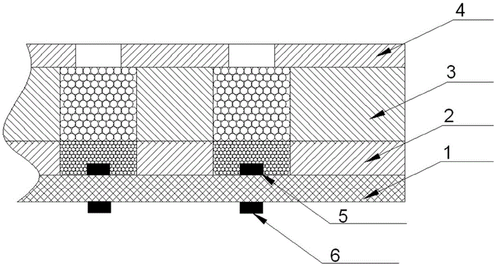
[0025] The solid micro thruster structure of the present invention mainly includes an ignition circuit layer, an ignition powder layer, a combustion chamber layer and a nozzle layer. Thruster array size is 10×10 (10 columns, 10 rows), 100×100 (100 columns, 100 rows).

[0026] 1 Solid Micro Thruster Array Structure

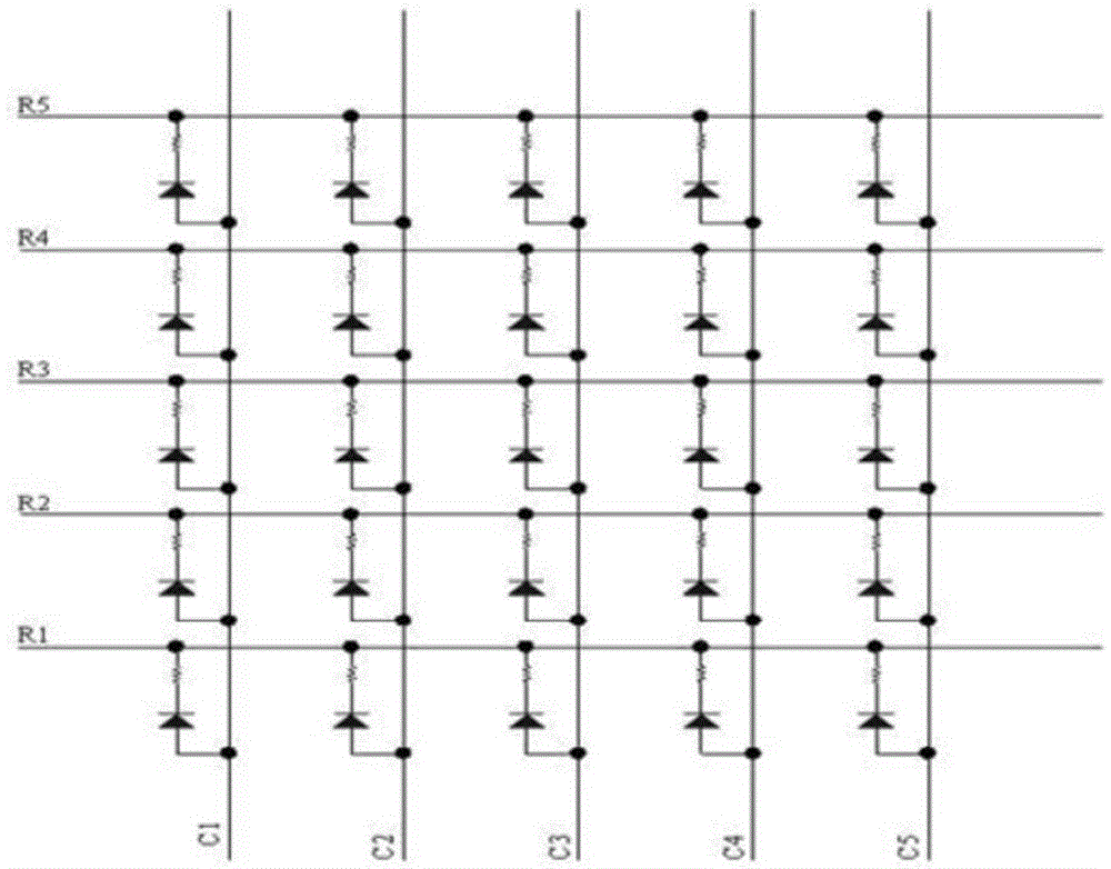
[0027] (1) Micro thruster array ignition circuit

[0028] The ignition circuit consists of a two-layer design, the upper layer is a resistor, and the lower layer is a diode, which are connected through row lines and column lines. One end of each heating resistor is connected to the anode of a diode, and the other end of the heating resistor is connected to the row line. The cathode of the diode The connection is on the column line; the row line and the column line are respectively distributed in different integrated circuit boards and do not affect each other. In order to distinguish it from the independent ignition circuit, this kind of ignition circuit is calle...


PUM


Abstract

A solid micro-thruster array structure for experiments comprises an ignition circuit layer, an ignition powder layer, a combustor layer and a spraying pipe layer, wherein the ignition circuit layer is located on the bottommost layer and is an array of M rows and N columns composed of M*N ignition circuits, M and N are positive integers and no less than two; the ignition powder layer is arranged above the ignition circuit layer and comprises M*N ignition powder chambers; each ignition powder chamber corresponds to one ignition circuit and is filled with gunpowder; the combustor layer is arranged above the ignition powder layer and comprises M*N combustors; each combustor corresponds to one ignition powder chamber and is filled with solid propellants; the spraying pipe layer is arranged above the combustor layer and comprises M*N spraying pipes; each spraying pipe corresponds to one combustor. The solid micro-thruster array structure for experiments can be applied to development of solid micro-thruster arrays, and research such as small-critical dimension propelling, micro-scale combustion, micro flow and control systems of micro-thrusters.

Description

technical field [0001] The invention relates to a solid micro-thruster array structure, which can be applied to the development of solid micro-thruster arrays, and can be used in the research of micro-thruster small critical size propulsion, micro-scale combustion, micro-flow, control systems, etc., which can greatly reduce development costs, development cycle, etc. Background technique [0002] In recent years, with the development of micro-nano, microelectronics and other technologies, micro-nano satellites are becoming one of the most active research directions in the aerospace field with a new concept and new design ideas. Micro-nano satellites have the characteristics of short development cycle, low investment and operating costs, low risk, and high flexibility. Space missions for which satellites are incapable. [0003] With the development of various supporting technologies of micro-nano satellites, it is transforming from flight verification to innovative applicati...

Claims


Application Information

Patent Timeline
Patent Type & Authority Patents(China)
IPC IPC(8): F02K9/96
Inventor 刘旭辉魏延明陈君龙军官长斌卢国权杨灵芝
Owner BEIJING INST OF CONTROL ENG
Why Eureka
Try Eureka