Fiber Bragg Grating Displacement Sensor

A technology of displacement sensor and optical fiber grating, which is applied in the direction of instruments, optical devices, measuring devices, etc., can solve the problems of reducing the measurement accuracy of sensors, large sensor size, and easy to break the grating, so as to avoid chirp phenomenon and high precision , Monitoring the effect of data stabilization

Active Publication Date: 2018-06-22
江西云沛科技发展有限公司
View PDF4 Cites 0 Cited by
  • Summary
  • Abstract
  • Description
  • Claims
  • Application Information

AI Technical Summary

Problems solved by technology

At present, a lot of work has been done on the fiber grating displacement sensor at home and abroad: using a curved elastic beam, the displacement is converted to the strain of the grating through the deformation of the beam, and the central wavelength of the fiber grating changes when the fiber grating is compressed or stretched. The amount of change is a function of the displacement to obtain the actual displacement; straight pull the grating, fix one end of the grating, and connect the other end to the mobile end, but this method has a very small range (0.6mm), and it is easy to break the grating
The cantilever beam structure adopts double fiber gratings pasted on the upper and lower surfaces of the cantilever beam to realize temperature compensation, but the sensor size of this method is large, and the wedge-shaped block is easy to cause vertical movement when sliding horizontally. Under the same horizontal displacement, the vertical A small movement in the direction will change the deflection of the cantilever beam, which will change the wavelength of the grating and reduce the measurement accuracy of the sensor

Method used


Image

  • Fiber Bragg Grating Displacement Sensor
  • Fiber Bragg Grating Displacement Sensor
  • Fiber Bragg Grating Displacement Sensor

Examples


Embodiment Construction

[0022] The present invention will be described in detail below in conjunction with the accompanying drawings and specific embodiments.

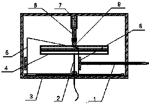
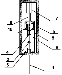
[0023] figure 1 , figure 2 Respectively is the front view of the fiber grating displacement sensor of the present invention, side view sectional schematic diagram

[0024] refer to figure 1 , figure 2 A preferred embodiment of the fiber grating displacement sensor of the present invention shown in, the fiber grating displacement sensor of the present invention comprises: 1, measuring rod; 2, fiber Bragg grating; 3, track; 4, elastic alloy member; 5, level Sliding block; 6. Guide shaft; 7. Bearing; 8. Connecting device; 9. Slidable support.

[0025] Such as figure 1 , figure 2 As shown in , the upper end of the elastic alloy member 4 is connected with the guide shaft 6, and the lower end is connected with the fiber grating 2; the measuring rod 1 passes through the horizontal sliding block 5 horizontally and is fixedly connected with t...


PUM


Abstract

The invention discloses a high-sensitivity fiber Bragg grating displacement sensor, which comprises a metal packaging shell and is characterized by further comprising a fiber Bragg grating, a measuring rod, a bearing, a track, a guide shaft, an elastic alloy component, a horizontal sliding block, a connecting device and a slidable support, wherein one end of the metal packaging shell is provided with the bearing and the guide shaft, and the other end is provided with the horizontal track; the guide shaft is connected with the elastic alloy component and contacted with the horizontal sliding block; the elastic alloy component is internally provided with the tensioned grating; and the horizontal sliding block is fixed with the measuring rod through the connecting device and connected with the track. The fiber Bragg grating displacement sensor has the beneficial effects that variations in displacement can be monitored accurately, the sensitivity is high, and the size is small compared with common fiber Bragg grating displacement sensors.

Description

technical field [0001] The invention relates to the sensing field of fiber grating technology, in particular to a fiber grating displacement sensor. Background technique [0002] Displacement sensors, also known as linear sensors, include a variety of categories, including capacitive displacement sensors, inductive displacement sensors, photoelectric displacement sensors, ultrasonic displacement sensors, and Hall displacement sensors. Common displacement measurement methods include mechanical measurement, electromagnetic measurement and laser measurement. Mechanical measurement has low precision and slow speed, making it inconvenient for on-line measurement; electromagnetic measurement is susceptible to electromagnetic interference, which is not conducive to engineering applications; laser measurement has high precision, but is constrained by the straight-line propagation of light, and is not suitable for on-site applications. Electrical sensors have poor ability to resist ...

Claims


Application Information

Patent Timeline
Patent Type & Authority Patents(China)
IPC IPC(8): G01B11/02
Inventor 周峰崔理纲户家喻
Owner 江西云沛科技发展有限公司
Why Eureka
Try Eureka