
A hierarchical spatial position description method and device based on voronoi diagram and landmarks

A spatial location and hierarchical technology, applied in the direction of instruments, calculations, electrical digital data processing, etc., can solve the problems of time-consuming, unfavorable to quickly find the spatial location of the target object, and the inability to establish spatial relationships with multiple landmarks, so as to improve efficiency Effect

Inactive Publication Date: 2018-03-30
HARBIN INST OF TECH SHENZHEN GRADUATE SCHOOL
View PDF2 Cites 0 Cited by
  • Summary
  • Abstract
  • Description
  • Claims
  • Application Information

AI Technical Summary

Problems solved by technology

[0003] However, in the existing spatial position description method, the spatial position of the target object only adopts a hierarchical reference system, which is not conducive to quickly find the spatial position of the target object
The reason is that the existing spatial location description method has only one layer, and the spatial location of the target object can only establish a spatial relationship with the nearest landmark, and cannot establish a spatial relationship with multiple nearby landmarks, so it can only establish a spatial relationship with the nearest landmark create spatial relationships
The spatial knowledge that people acquire is all blocks centered on landmarks, and there are gaps between the blocks. At this time, the subsidiary area of ​​the landmark is the area of ​​the landmark. If the nearest landmark is missing, the user cannot locate it through the nearest landmark. The spatial position of the target object needs to be searched for the spatial position of the target object step by step, so it takes time and is not conducive to quickly find the spatial position of the target object

Method used


Image

  • A hierarchical spatial position description method and device based on voronoi diagram and landmarks
  • A hierarchical spatial position description method and device based on voronoi diagram and landmarks
  • A hierarchical spatial position description method and device based on voronoi diagram and landmarks

Examples


Embodiment 1

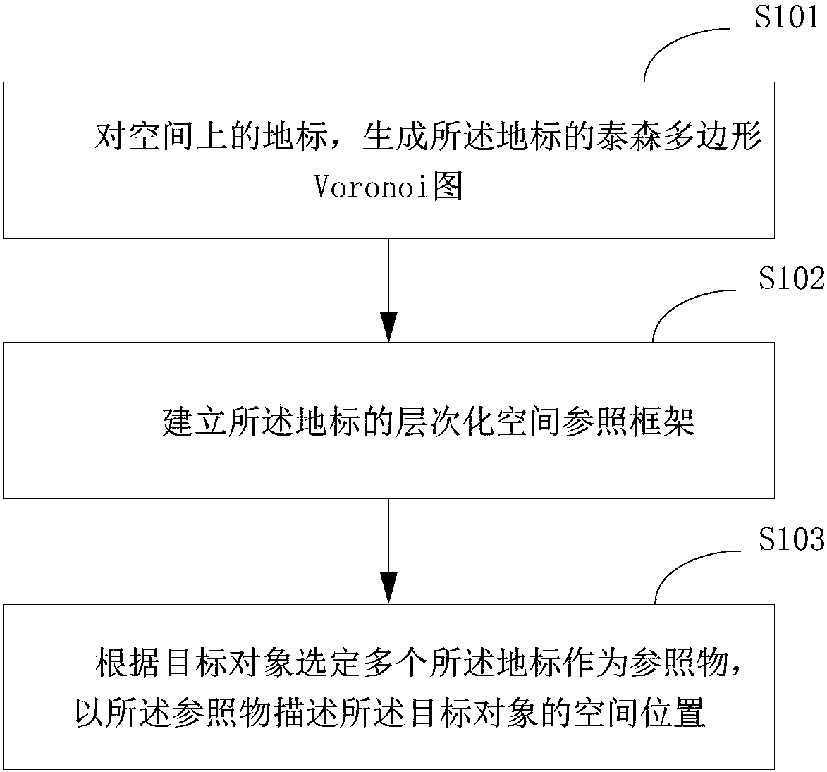
[0024] figure 1 It is an implementation flowchart of the hierarchical spatial position description method based on the Voronoi diagram and landmarks provided by the embodiment of the present invention, and is described in detail as follows:

[0025] In step S101, for a landmark in space, a Voronoi diagram of the landmark is generated;

[0026] In step S102, establishing a hierarchical spatial reference frame of the landmark;

[0027] Based on the Voronoi diagram, a hierarchical spatial reference frame of the landmarks is established.

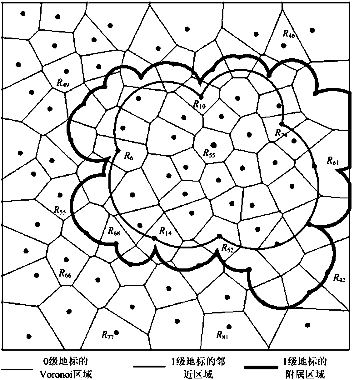
[0028] Among them, the spatial hierarchical model based on the Voronoi diagram means that when one Voronoi unit is contained inside another Voronoi unit, the boundary of the latter is limited by the boundary of the former, and the low-level regional management center falls into the high-level area Inside.

[0029] In step S103, a plurality of landmarks are selected as reference objects according to the target object, and a hierarchical spatia...

Embodiment 2

[0034] This embodiment describes the implementation process of establishing a hierarchical spatial reference frame, which is described in detail as follows:

[0035] Generate adjacent regions based on the Voronoi diagram for the landmarks in space, and the subsidiary region S (R, 0) of each landmark R is the adjacent regions;

[0036] Cycle k from 1 to n, k is the granularity;

[0037] For all landmarks in space, using landmarks where L(R)>=k as a set, generate the adjacent area;

[0038] For landmarks R with L(R)>=k, obtain all landmarks of all k-1 levels that fall within the adjacent area of ​​landmark R;

[0039] The subsidiary area S(R, k) of landmark R on layer k is the sum of all the landmarks (including R itself) of level k-1 that fall within the adjacent area of ​​the landmark at level k-1;

[0040] Among them, the subsidiary area of ​​the landmark at the j (j<=i) layer is denoted as S(R, j);

[0041] Among them, L(R) represents the level of landmark R.

[0042] Am...

Embodiment 3

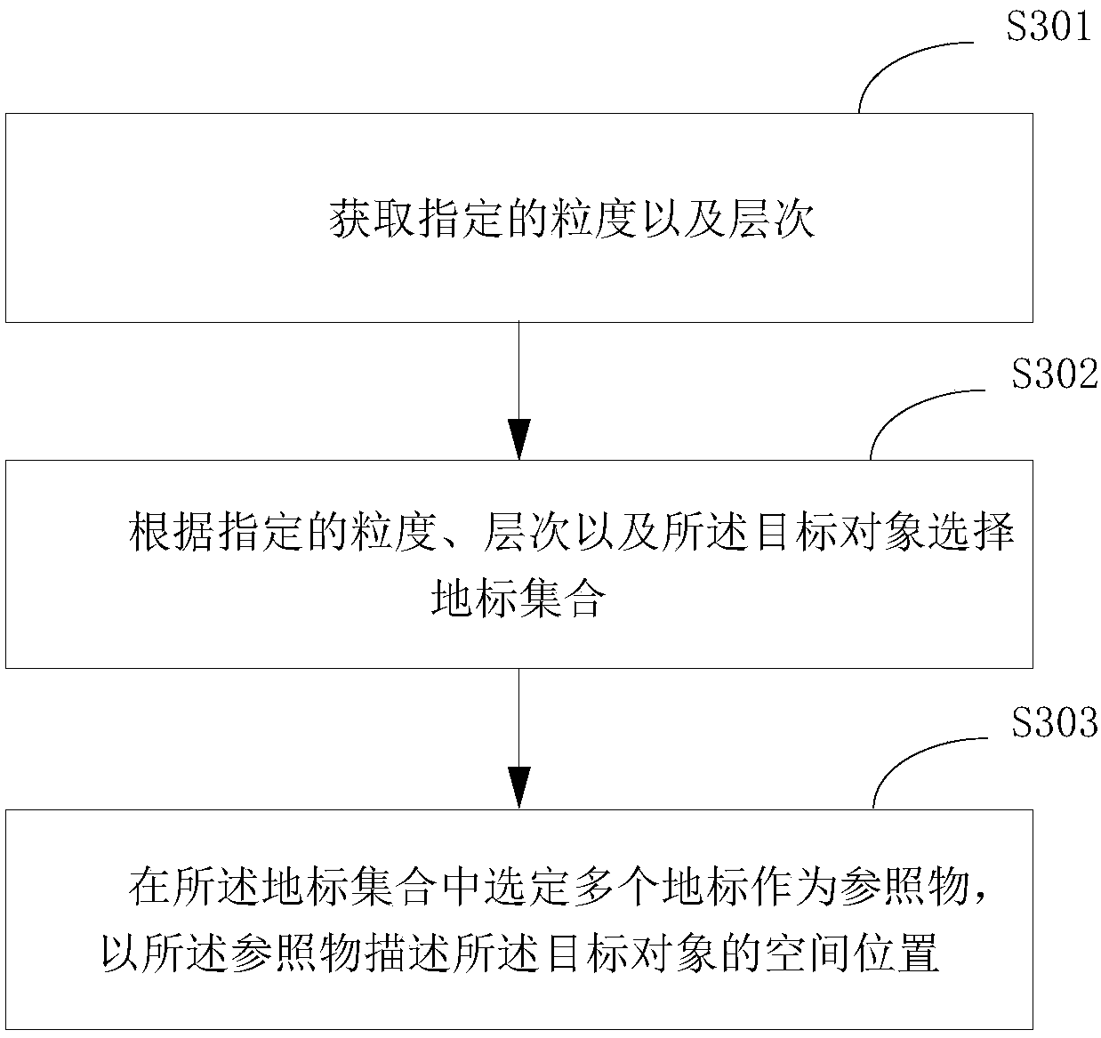
[0046] image 3 It is the implementation flowchart of step S103 of the hierarchical spatial position description method based on the Voronoi diagram and landmarks provided by the embodiment of the present invention, and is described in detail as follows:

[0047] In step S301, the specified granularity and level are acquired;

[0048] In step S302, select a landmark set according to the specified granularity, level and the target object;

[0049] In step S303, a plurality of landmarks are selected in the landmark set as reference objects, and a hierarchical spatial position description of the target object is established with the reference objects.

[0050] refer to Figure 4 , Figure 4 It is a better sample diagram of the positioning target object provided by the embodiment of the present invention.

[0051] In the case where the granularity requirement is 1, T 1 Several first-level landmarks adjacent to it will be used as candidate reference objects, and an appropriate...


PUM


Abstract

The present invention is applicable to the field of landmark description, and provides a hierarchical spatial position description method and device based on Voronoi diagrams and landmarks. The hierarchical spatial position description method based on Voronoi diagrams and landmarks includes: for spatial landmarks, generating The Voronoi diagram of the landmarks; establishing a hierarchical spatial reference frame of the landmarks; selecting a plurality of the landmarks as reference objects according to the target object, and establishing a hierarchical spatial position description of the target object with the reference objects. The invention solves the problem that the spatial position of the target object is described only by a hierarchical reference system, which does not conform to the human's spatial cognition. A hierarchical spatial reference system is established through the Voronoi diagram, and automatically generated based on the reference system. The description of the spatial position of the target object is in line with the hierarchy of human spatial cognition and habits in different scenarios, thereby improving the efficiency of target object positioning.

Description

technical field [0001] The invention belongs to the field of landmark description, in particular to a hierarchical spatial position description method and device based on Voronoi diagrams and landmarks. Background technique [0002] A landmark is a building or natural object with unique geographical characteristics in a certain place. When people go to an unfamiliar environment, because they are not familiar with the environmental space, they attach the perceived spatial position to those prominent landmarks. Generally speaking, by anchoring to a single landmark, the spatial position is described, which is convenient for users. Find the spatial location of the target object. [0003] However, in the existing spatial position description methods, the spatial position of the target object only adopts a hierarchical reference system, which is not conducive to quickly find the spatial position of the target object. The reason is that the existing spatial location description m...

Claims


Application Information

Patent Timeline
Patent Type & Authority Patents(China)
IPC IPC(8): G06F17/30
Inventor 龚咏喜林姚宇王耀武陈占军
Owner HARBIN INST OF TECH SHENZHEN GRADUATE SCHOOL
Learn More