
Electromagnetic induction device and touch positioning method thereof

A technology of electromagnetic induction and electromagnetic pen, which is applied in the direction of electric digital data processing, instrumentation, input/output process of data processing, etc., and can solve problems such as loss of touch points, delayed positioning, etc.

Active Publication Date: 2011-08-03
BEIJING HANWANG PENGTAI TECH CO LTD
View PDF4 Cites 25 Cited by
  • Summary
  • Abstract
  • Description
  • Claims
  • Application Information

AI Technical Summary

Problems solved by technology

In this way, when the electromagnetic pen quickly clicks on the electromagnetic induction antenna board, it is easy to cause the loss of the touch point and the delayed positioning due to the long scanning time of the coil.
[0005] At present, in the case of a large number of coils on the electromagnetic induction antenna board, there is no simple and feasible method that can effectively improve the positioning speed and accuracy of the electromagnetic pen of the electromagnetic handwriting system

Method used


Image

  • Electromagnetic induction device and touch positioning method thereof
  • Electromagnetic induction device and touch positioning method thereof
  • Electromagnetic induction device and touch positioning method thereof

Examples


Embodiment 1

[0138] Suppose, the area of ​​the antenna board is 40*50, 40 transmitting coils are used, p=40; 50 receiving coils are used, q=50; n1=2, n2=2; ADD=3; m=4; the electromagnetic pen signal The preliminary positioning threshold is t1, and the precise positioning threshold is t2.

[0139] S101: strobe the two initial transmitting coils Tx respectively 0 ,Tx 20 , and two initial receiving coils Ry 0 ,Ry 20 .

[0140] Opentx(0); Opentx(20); Openry(0); Openry(20);

[0141] S102: Scan Tx separately 0 ,Tx 20 ,Ry 0 ,Ry 20 Combination of coils, detecting and recording the electromagnetic pen signal of each pair of coils.

[0142] Scan the following coil combinations individually:

[0143] {Opentx(0), Openry(0)};

[0144] {Opentx(0), Openry(20)};

[0145] {Opentx(20), Openry(0)};

[0146] {Opentx(20), Openry(20)};

[0147] S103: Judging whether all antenna plate areas have been scanned, if all antenna plate areas have been scanned, then calculate the maximum value of the dete...

Embodiment 2

[0173] The antenna area is 40*50, 40 transmitting coils are used, p=40; 50 receiving coils are used, q=50; ADD=3; m=4, the preliminary positioning threshold of the electromagnetic pen signal is t1, and the precise positioning threshold is t2 . Steps S101 to S103 are the same as those in Embodiment 1 and will not be described in detail. The difference between this embodiment and Embodiment 1 is that in step 103, all antenna board areas have been scanned.

[0174] The following coils are gated: {Opentx(0), Opentx(20); Openry(0), Openry(20)}.

[0175] S105: Calculate the maximum value (MAX) of the detected electromagnetic pen signal, and preliminarily determine the intersection point of the transmitting coil and receiving coil corresponding to the maximum value of the electromagnetic pen signal as the position of the electromagnetic pen.

[0176] Assume that the combination of the transmitting coil and the receiving coil corresponding to the maximum value of the electromagnetic...

Embodiment 3

[0185] The difference from Embodiment 1 and Embodiment 2 is that the antenna area of ​​Embodiment 3 is composed of an odd number of transmitting coils and receiving coils, assuming that the antenna area is 19*19, 19 transmitting coils are used, and p=19; the receiving coil Take 19 pieces, q=19; ADD=3; m=4, the preliminary positioning threshold of the electromagnetic pen signal is t1, and the precise positioning threshold is t2.

[0186] In this embodiment, the number of transmitting coils and receiving coils is an odd number. Preferably, the first transmitting coil Tx is selected separately 0 and the first receiving coil Ry 0 , both n1 and n2 are even numbers. In this embodiment, n1=2 and n2=2 are taken as an example for illustration.

[0187] Separately strobe the first transmit coil Tx 0 , and at the same time sequentially select the direction of the receiving coil to scan the electromagnetic pen signal to detect the electromagnetic pen signal; and,

[0188] Separately st...


PUM


Abstract

The invention discloses an electromagnetic induction device and a touch positioning method thereof, belonging to the field of electromagnetic handwritten input. The touch positioning method provided by the invention comprises the following steps of: simultaneously gating at least two groups of transmitter coils and receiving coils for scanning, detecting and recording an electromagnetic pen signal; primarily positioning an electromagnetic pen according to the maximum value of the detected electromagnetic pen signal and a coil combination corresponding to the maximum value after all boundary transmitter coils and boundary receiving coils in an antenna plate zone are scanned; and accurately positioning the electromagnetic pen according to the coil combination corresponding to the maximum value of the electromagnetic pen signal if the maximum value of the electromagnetic pen signal is smaller than a preset initial positioning threshold value, or else processing the combination of the receiving coils and the transmitter coils corresponding to the maximum value of the electromagnetic pen signal to confirm the position of the electromagnetic pen. The method provided by the invention can be adopted to rapidly realize the accurate positioning of the electromagnetic pen and can effectively avoid the problems of contact loss, delayed positioning, and the like when the electromagnetic pen rapidly moves.

Description

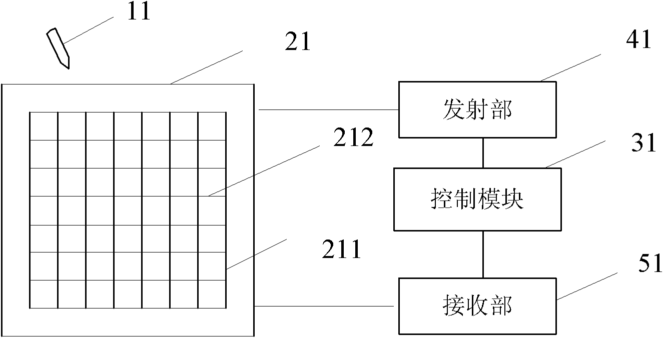
technical field [0001] The invention belongs to the field of electromagnetic handwriting input, in particular to an electromagnetic induction device and a touch positioning method thereof. Background technique [0002] Electromagnetic induction handwriting technology is favored by the market due to its high positioning accuracy, ability to detect the pressure of the user's pen, and a certain induction height. It is widely used in e-books, tablet PCs, mobile phones and other devices. [0003] The positioning method of the electromagnetic induction handwriting system (referred to as the electromagnetic handwriting system), that is, the principle of determining the position of the electromagnetic pen is roughly as follows: the transmitting coil on the electromagnetic induction antenna board sends out an excitation signal, and the resonant circuit in the electromagnetic pen is excited by the excitation signal. Electromagnetic induction signal, the electromagnetic induction signa...

Claims


Application Information

Patent Timeline
IPC IPC(8): G06F3/046
Inventor 赵磊
Owner BEIJING HANWANG PENGTAI TECH CO LTD
Learn More