Electric junction box

An electrical junction box and frame technology, applied to electrical components and other directions, can solve the problems of poor assembly workability, difficulty in accurate positioning of multiple locked parts 5, etc., and achieve the effects of easy assembly, simplified structure, and improved rigidity

Active Publication Date: 2015-07-22
YAZAKI CORP
View PDF6 Cites 2 Cited by
  • Summary
  • Abstract
  • Description
  • Claims
  • Application Information

AI Technical Summary

Problems solved by technology

[0011] The above electrical junction box 301 has the problem that when assembling the modules 303A, 303B on the frame 302, it is difficult to accurately position the plurality of locked parts 5 on the corresponding locking parts 4, and the assembly workability is poor.

Method used


Image

  • Electric junction box
  • Electric junction box
  • Electric junction box

Examples


Embodiment Construction

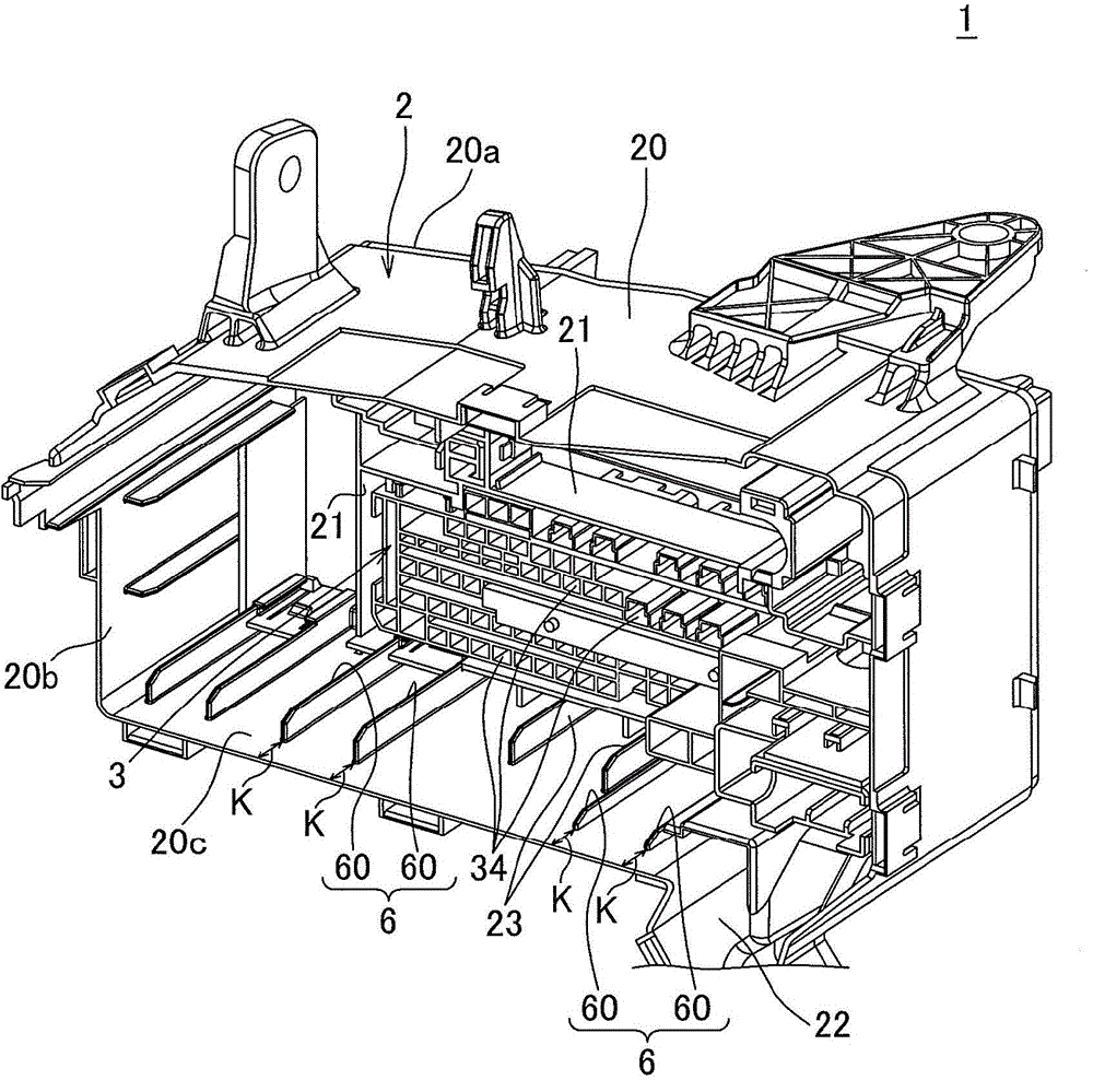
[0036] refer to Figure 1~6 An "electric junction box" according to one embodiment of the present invention will be described. figure 1 The illustrated electrical junction box 1 is mounted on an automobile and mainly performs power distribution. This electrical junction box 1 includes: a frame 2 made of synthetic resin having a frame-shaped peripheral wall 20 ; and a plurality of modules made of synthetic resin assembled inside the frame 2 . In addition, in this specification, one module 3 is demonstrated on behalf of a plurality of modules.

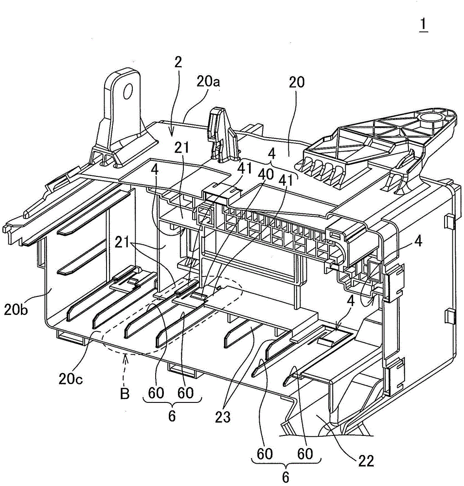
[0037] The framework 2 as figure 2 As shown, there is a peripheral wall 20 ; and a plurality of inner walls 21 dividing the inner space of the peripheral wall 20 . The peripheral wall 20 is formed in a cylindrical shape as described above, and has openings 20a, 20b.

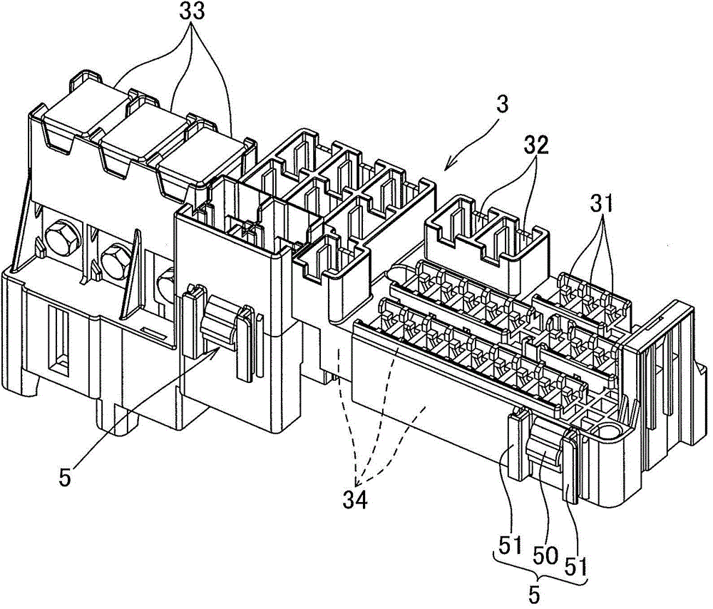
[0038] The above module 3 as image 3 As shown, a wire insertion portion 34 is provided on one side, and electronic component mounting portions 31 , 32 , and 33 for ...


PUM


Abstract

The invention provides an electric junction box which can easily assemble a module to a framework. The electronic junction box (1) comprises the framework (2) which is provided with a frame-shaped peripheral wall (20), and the module (3) which is inserted into the inner side of the peripheral wall (20) from an opening part (20b) of the peripheral wall (20) and assembled to the framework (2). The framework (2) is provided with four locking parts, and the module (3) is provided with four locked parts clamped and stopped by the locking parts. Furthermore, the framework (2) is provided with a guide structure (6), and the guide structure (6) guides the locked parts from a side of the opening part (20b) to the corresponding locking parts. The guide structure (6) comprises a pair of ribs (60), and the ribs (60) are connected with the inner surface of the peripheral wall (20) and extends from a position near the opening part (20b) to the locking parts, so the locked parts are located between the opening part (20b) and the locking parts in a freely sliding manner. The guide structure (6) is also used for enhancing rigidity of the framework (2).

Description

technical field [0001] The present invention relates to an electrical junction box that is mounted on an automobile and mainly performs power distribution. Background technique [0002] Electrical junction boxes mounted on automobiles having various structures, for example, electric junction boxes disclosed in Patent Documents 1 and 2 include a frame having a frame-shaped peripheral wall and a structure of a module assembled inside the frame. junction box. in addition, Figure 7 It is an exploded view of a conventional electrical junction box disclosed in Patent Document 2. FIG. [0003] Such as Figure 7 As shown, the electrical junction box 301 includes: a frame 302 having a frame-shaped peripheral wall 320 ; The modules 303A and 303B are inserted with electric wires 308 on one side, and electronic components such as relays and fuses are loaded on the other side. [0004] The frame 302 is provided with a plurality of locking parts 4 , and the modules 303A and 303B are p...

Claims


Application Information

Patent Timeline
Patent Type & Authority Applications(China)
IPC IPC(8): H02G3/08
Inventor 赤堀正裕小野田健
Owner YAZAKI CORP
Why Eureka
Try Eureka