Sealing system
A technology for sealing components and orifices, which is used in the system and wiring of pipes and pipes, and can solve problems such as damage to electronic components and electric shocks for staff.
- Summary
- Abstract
- Description
- Claims
- Application Information
AI Technical Summary
Problems solved by technology
Method used
Image

Examples
Embodiment Construction
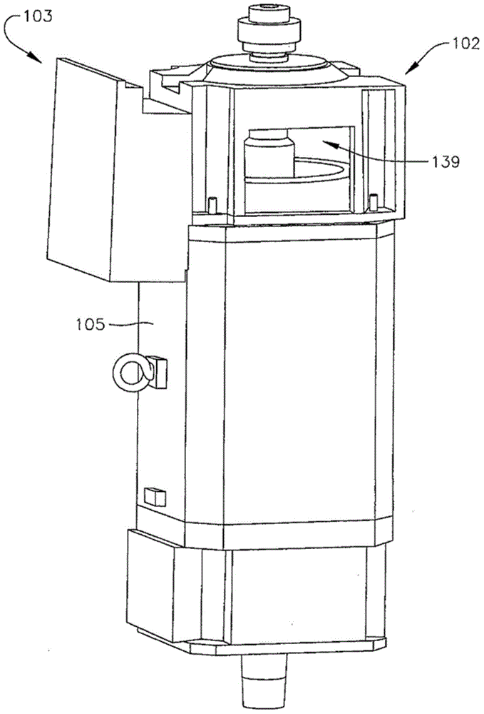
[0015] The present invention relates to a system for creating a watertight seal around one or more flexible longitudinal members extending through a panel section. refer to figure 1 In the illustrated embodiment, sealing system 100 is configured to create a watertight seal around a plurality of various wires, cables, conduits, pipes, hoses and / or conduits 101 (also referred to herein as "flexible longitudinal members"), as described above. A flexible longitudinal member extends from the top drive motor housing 102 to a junction box 103 connected to the side of the motor housing 102 . Junction box 103 houses various electronic components (eg, bus bars and other electronic disconnects). Wiring, cables, conduit and / or tubing 101 extending from top drive motor housing 102 terminates at a bus bar or other electrical disconnect housed within junction box 103 .
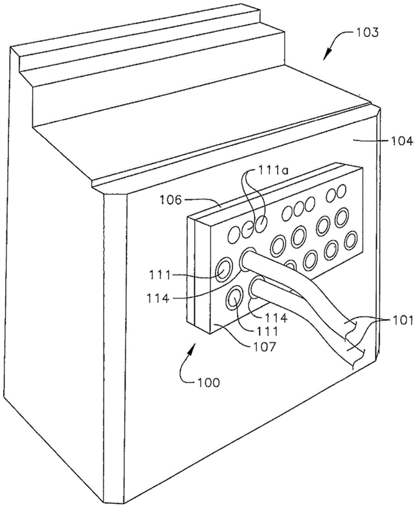
[0016] refer to figure 2 In the illustrated embodiment, the sealing system 100 is attached to the wall 104 of the junc...
PUM
 Abstract
Description
Claims
Application Information
PatSnap Eureka turns technology decisions into work you can execute. Powered by our Innovation Knowledge Graph, it runs expert workflows across engineering, life sciences, materials and intellectual property. Get your review-ready output in minutes.


