
Wind parameter indication

A parameter and indication technology, which is applied to aircraft indication devices, uses multiple variables to indicate weather conditions, uses re-radiation and other directions, and can solve problems such as inaccuracy and sensitivity

Active Publication Date: 2015-07-22
VENTUS PROD DEV & CONSULTING
View PDF10 Cites 16 Cited by
  • Summary
  • Abstract
  • Description
  • Claims
  • Application Information

AI Technical Summary

Problems solved by technology

However, sonic anemometers are sensitive to inaccuracies during precipitation (eg, rainy weather) and may also require compensation for support structure effects

Method used


Image

  • Wind parameter indication
  • Wind parameter indication
  • Wind parameter indication

Examples


Embodiment Construction

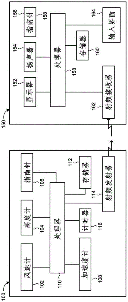
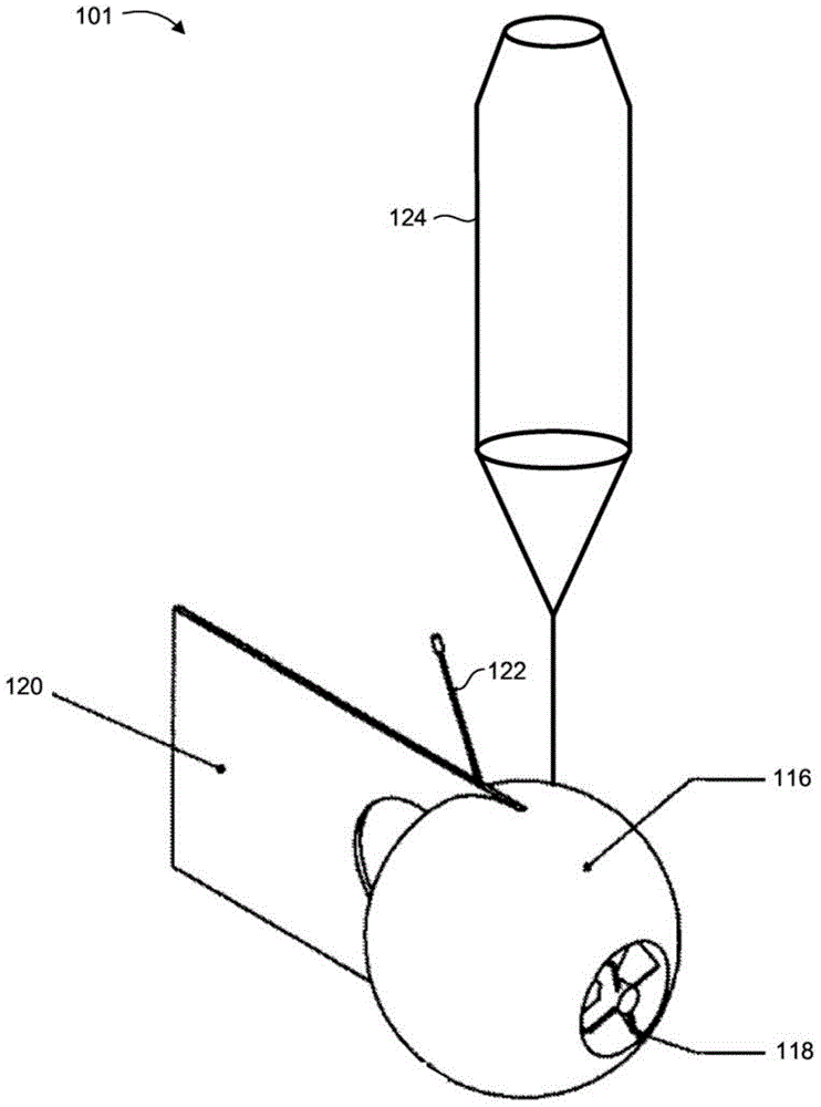
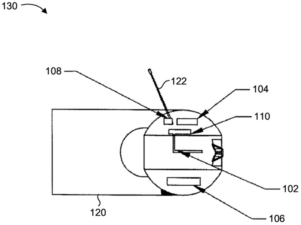
[0028] The disclosed technology overcomes the disadvantages of the prior art by providing a new wind parameter indicating device and a new wind parameter indicating system comprising said device and a receiver unit. The wind parameter indicating device is tracked in the air, eg dropped from an aircraft during flight, and provides wind parameter measurements, such as wind speed and direction, as the device falls towards the ground surface. Selected wind parameter values ​​may be transmitted from the wind parameter indicating device to a remotely located receiver unit. The wind parameter indicating system may be used for aircraft landing assistance, firefighting, and other potential applications.

[0029] now refer to figure 1 , which is a block diagram of a wind parameter indicating system constructed and operative in accordance with an embodiment of the disclosed technology. The wind parameter indicating system includes a wind parameter indicating device 100 and a receiver u...


PUM


Abstract

Wind parameter indication device and method for providing an indication of wind speed and wind direction. The device is deployed along an aerial trajectory toward a ground surface, such as after being ejected from an aircraft in flight. The device includes an anemometer, an altimeter, a compass, a processor and a transmitter. The anemometer obtains local wind speed and local wind direction measurements along the trajectory. The altimeter obtains altitude measurements along the trajectory. The compass obtains direction measurements along the trajectory. The device may further include an accelerometer, for obtaining acceleration measurements along the trajectory. The processor determines a wind speed value and a wind direction value associated with a predetermined altitude of the device. The transmitter transmits the determined wind speed value and wind direction value to a remotely located receiver. The device may further include a stabilizing decelerator to stabilize and decelerate the device along the trajectory.

Description

technical field [0001] The disclosed technology generally relates to wind speed and direction indicators and aircraft landing assistance. Background technique [0002] The main feature of a helicopter is its ability to perform a landing in almost any location and does not necessarily require a dedicated runway like many other types of aircraft. A typical aircraft landing includes the pilot receiving the necessary landing information from an operator located at a nearby aircraft control station and / or the airport at which the landing is to be made. If the pilot lands the aircraft at a remote location where the necessary landing information cannot be obtained from an external source, the information must be obtained by other means. Key components of this information are various parameters related to the wind conditions at the desired landing site, such as wind speed and direction. Wind parameters must be known with a sufficiently high level of accuracy. There can be signifi...

Claims


Application Information

Patent Timeline
Patent Type & Authority Applications(China)
IPC IPC(8): G01S1/00G01S19/15G01S5/00G01W1/00B64D17/00G01S17/86
CPCG01S7/003G01F1/76G01S19/15B64D1/08G01C5/00G01W1/02B64D45/00B64D17/00G01S17/95G01S19/14G01S17/023G01S17/88G01W1/08G01C17/00G01S17/86Y02A90/10
Inventor I·浩方Y·格劳兹曼I·盖里姆
Owner VENTUS PROD DEV & CONSULTING
Learn More