Dynamic diagnosis support information generation system

A technology for information generation and diagnostic assistance, applied in the direction of diagnosis, informatics, medical informatics, etc., can solve the problems of time-consuming, increased processing time, increased data capacity, etc., and achieve the effect of shortening the processing time

Active Publication Date: 2015-07-29
KONICA MINOLTA MEDICAL & GRAPHICS INC
View PDF5 Cites 2 Cited by
  • Summary
  • Abstract
  • Description
  • Claims
  • Application Information

AI Technical Summary

Problems solved by technology

In the warping process, since the alignment is generally performed according to the spatial density change caused by the structure in the lung field, it is necessary to faithfully (uniformly) reproduce the density of the structure for all frames of images. The difference in the output of each pixel (therefore, it is necessary to correct the difference by performing various correction processes such as offset (offset) correction processing, gain correction processing, defective screen correction processing, and hysteresis correction processing), and the correction process takes time. In addition, in order to perform high-precision warping processing, the higher the precision, the more high-resolution images are required, so a detector with a small pixel size is required, which increases the data capacity of each frame of image and becomes the entire data to be processed. Large increase in capacity
Therefore, hardware such as a large-capacity memory and a high-speed processing CPU are required, and the processing time is also increased.

Method used


Image

  • Dynamic diagnosis support information generation system
  • Dynamic diagnosis support information generation system
  • Dynamic diagnosis support information generation system

Examples


no. 1 Embodiment approach

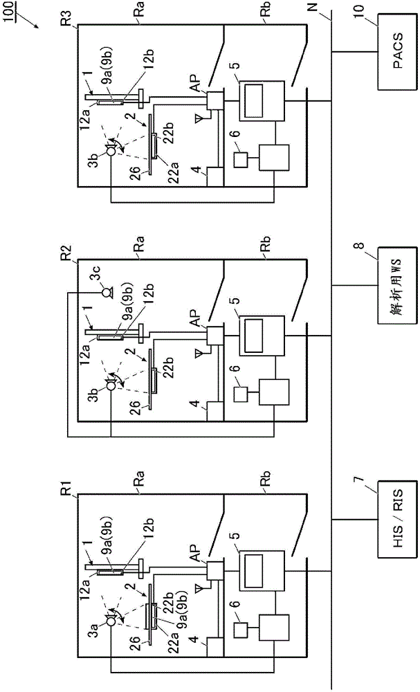
[0060] figure 1 It is a diagram showing the overall configuration of the auxiliary diagnostic information generating system 100 according to the first embodiment of the present invention.

[0061] figure 1 The illustrated imaging rooms R1 to R3 are rooms for performing dynamic imaging or still image imaging of the subject by irradiating radiation to the subject which is a part of the patient's body (ie, the imaging site of the patient).

[0062] Dynamic imaging refers to imaging in which a plurality of images are obtained by continuously irradiating a subject with radiation such as X-rays in a pulsed manner (that is, continuous imaging). Motion photography captures the movement of a subject that has periodicity, such as morphological changes such as expansion and contraction of the lungs accompanying respiratory movement, and heartbeats. A series of images obtained by this continuous shooting is called a moving image. In addition, a plurality of images constituting a moving...

no. 2 Embodiment approach

[0270] Next, a second embodiment of the present invention will be described.

[0271] First, the structure will be described.

[0272] Figure 17 The overall configuration of the auxiliary diagnostic information generating system 300 in the second embodiment is shown. The auxiliary diagnosis information generation system 300 is a system that uses the analysis server 30 of the analysis center to analyze moving images captured in small-scale facilities such as private hospitals and clinics, and provides the analysis results to the small-scale facilities. As described in the first embodiment, when the warping process can be omitted, it is not necessary to consider the pixel size of the FPD, the dynamic range of each pixel, and the like on the side of performing the analysis process. Therefore, irrespective of the type of FPD used in each facility, analysis processing can be provided in an open system as described below.

[0273] Such as Figure 17 As shown, the reception devi...


PUM


Abstract

A dynamic diagnosis support information generation system includes: a radiation generator capable of irradiating a pulsed radiation; a radiation detector which is provided with a plurality of detecting elements arranged in two-dimension, detects the pulsed radiation irradiated from the radiation generator at each of the plurality of detecting elements and generates frame images successively; and an analysis section which calculates and outputs a feature value relating to a dynamic image of a subject based on a plurality of frame images generated by radiographing the subject by using the radiation generator and the radiation detector, wherein the analysis section calculates the feature value relating to the dynamic image of the subject by corresponding pixels to each others representing outputs of a detecting element at a same position in the radiation detector among the plurality of the frame images.

Description

technical field [0001] The invention relates to a dynamic diagnosis auxiliary information generation system. Background technique [0002] In recent years, a dynamic photography of a subject using FPD (Flat Panel Detector) corresponding to dynamic images has been proposed, based on a series of frame images obtained through dynamic photography, feature quantities related to the dynamic are calculated, and This is a technique for providing physicians with diagnostic support information for early diagnosis (for example, refer to Patent Documents 1 and 2). [0003] [Patent Document 1] Japanese Unexamined Patent Publication No. 2003-298939 [0004] [Patent Document 2] Japanese Patent Laid-Open No. 2009-153678 [0005] Although both Patent Documents 1 and 2 are technologies related to diagnostic auxiliary information related to chest breathing, when analyzing feature quantities related to chest breathing movement, such as ventilation volume and blood flow, it is necessary to Mu...

Claims


Application Information

Patent Timeline
Patent Type & Authority Applications(China)
IPC IPC(8): A61B6/00G16H20/40G16H30/40
CPCA61B6/461G06T2207/30061A61B6/4233A61B6/54G06F19/321G06F19/3481G06T2207/10116A61B6/4494A61B6/40A61B6/507A61B6/563G06T7/0016A61B6/5264G06T7/2053G06T2207/10016A61B6/5217A61B6/4266G06T7/254G16H30/40G16H20/40G16H30/20
Inventor 村冈慎太郎岛田哲雄野地翔
Owner KONICA MINOLTA MEDICAL & GRAPHICS INC
Why Eureka
Try Eureka