Double-rotor pipeline type emulsifying machine

A pipeline type, double rotor technology, applied in the field of emulsifier, can solve the problems of high production cost and lack of promotion, and achieve the effect of good crushing effect

Active Publication Date: 2015-07-29
刘金辉
View PDF5 Cites 4 Cited by
  • Summary
  • Abstract
  • Description
  • Claims
  • Application Information

AI Technical Summary

Problems solved by technology

There is also a dual-rotor mode in the existing patented technology, but its complex feeding mode determines its high production cost, which offsets the benefits brought by the increase in line speed
Therefore, it has not been promoted in the market

Method used


Image

  • Double-rotor pipeline type emulsifying machine
  • Double-rotor pipeline type emulsifying machine
  • Double-rotor pipeline type emulsifying machine

Examples


Embodiment Construction

[0031] Below in conjunction with accompanying drawing and embodiment describe in detail:

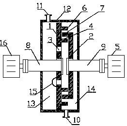
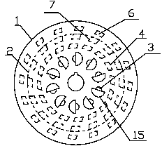
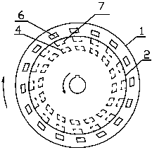
[0032] Such as Figure 1 to Figure 14As shown, the double-rotor pipeline type emulsifier of the present invention includes a housing 12, and the housing 12 is provided with an inner chamber, and the inner chamber of the housing 12 is provided with a left rotor and a right rotor, and the left rotor includes a left disk surface 1, a left rotor The right side of the disk surface 1 is provided with a first helical tooth 6 and a third helical tooth 4 in the circumferential direction, that is, the first helical tooth 6 and the third helical tooth 4 are respectively located on two concentric circles of the left disk surface 1, and the first helical tooth 6 is located on the On the radially outer side of the third helical tooth 4, the center of the left disc surface 1 is provided with a left shaft hole 17, the left shaft hole 17 is provided with a keyway, the left shaft 8 passes through the left...


PUM


Abstract

The invention discloses a double-rotor pipeline type emulsifying machine which comprises a casing, wherein an inner cavity is formed in the casing; a left rotor and a right rotor are arranged in the inner cavity of the casing; the left rotor comprises a left disc surface, first helical teeth and third helical teeth are arranged on the periphery of the right side surface of the left disc surface, and the first helical teeth are located on the radial outer sides of the third helical teeth; the right rotor comprises a right disc surface, second helical teeth are arranged on the periphery of the left side surface of the right disc surface and face the left side, and second tooth space is formed between every two second helical teeth; after the left rotor and the right rotor are fastened together, the slanting directions of the first helical teeth, the third helical teeth and the second helical teeth are the same, the second helical teeth are located between radial directions of the first helical teeth and the third helical teeth, the rotating direction of the left rotor is opposite to the slanting direction of the first helical teeth, and the rotating direction of the right rotor is the same with the slanting direction of the second helical teeth; the left rotor is provided with feeding through holes formed in the inner radial side of the third helical teeth; the left disc surface divides the inner cavity into a left cavity and the right cavity, a feeding port is formed in the left cavity, and the discharging port is formed in the right cavity. The double-rotor pipeline type emulsifying machine has good emulsifying effect and novel structure.

Description

technical field [0001] The invention relates to an emulsifying machine, in particular to a pipeline type emulsifying machine used for wet medium processing. Background technique [0002] Pipeline emulsifier is a common machine used for emulsification, homogenization and dispersion of products in industrial production. It can be used for highly dispersed multiphase liquids and rapid refinement of fixed particles. It is widely used in food, pharmaceutical, chemical and other fields. The pipeline type emulsifier in actual industrial practice is driven by the relative movement of the stator and the rotor that are engaged by the pair, and the material is impacted and sheared to achieve the purpose of emulsification, homogenization and dispersion. It is characterized by large processing capacity, continuous production on-line, and narrow particle size distribution range. For materials with good fluidity, no additional conveying power is required by the conveying pump, so it is wi...

Claims


Application Information

Patent Timeline
Patent Type & Authority Applications(China)
IPC IPC(8): B01F7/10B01F3/08B01F27/73
Inventor 刘金辉
Owner 刘金辉
Why Eureka
Try Eureka