[0040] Regarding the technology, means and effects adopted by the present invention, three preferred embodiments are described in detail in conjunction with the drawings, which are for illustrative purposes only, and are not limited by this structure in the patent application.
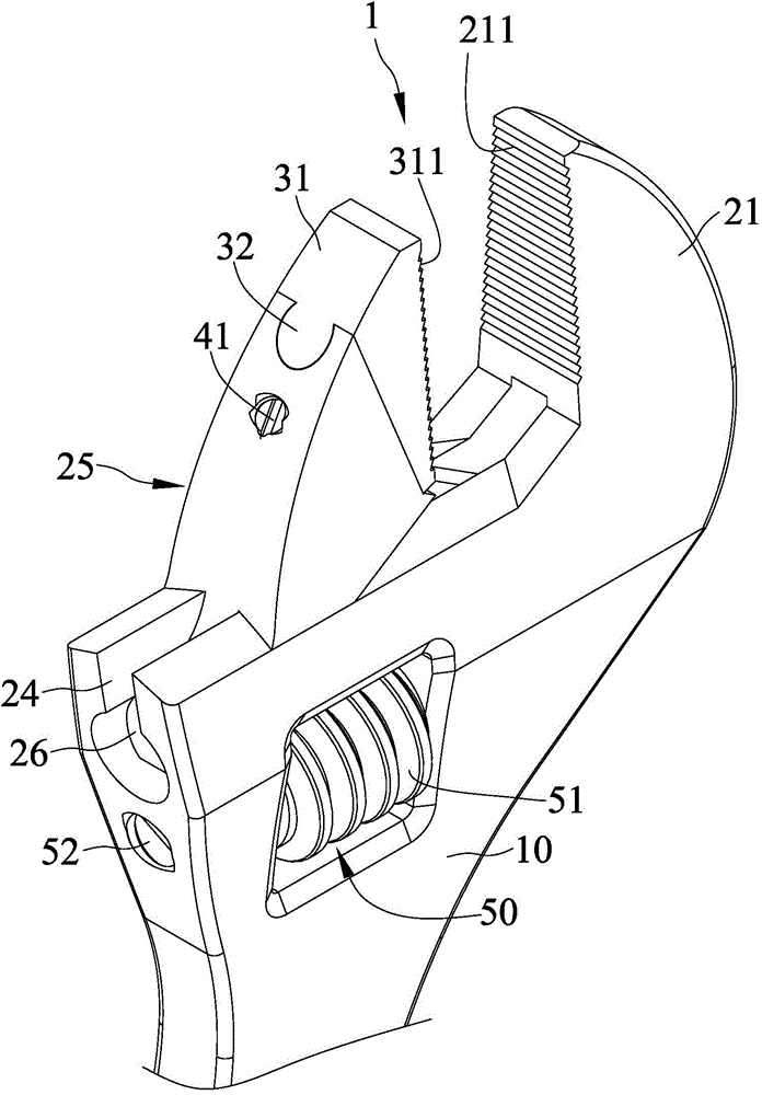
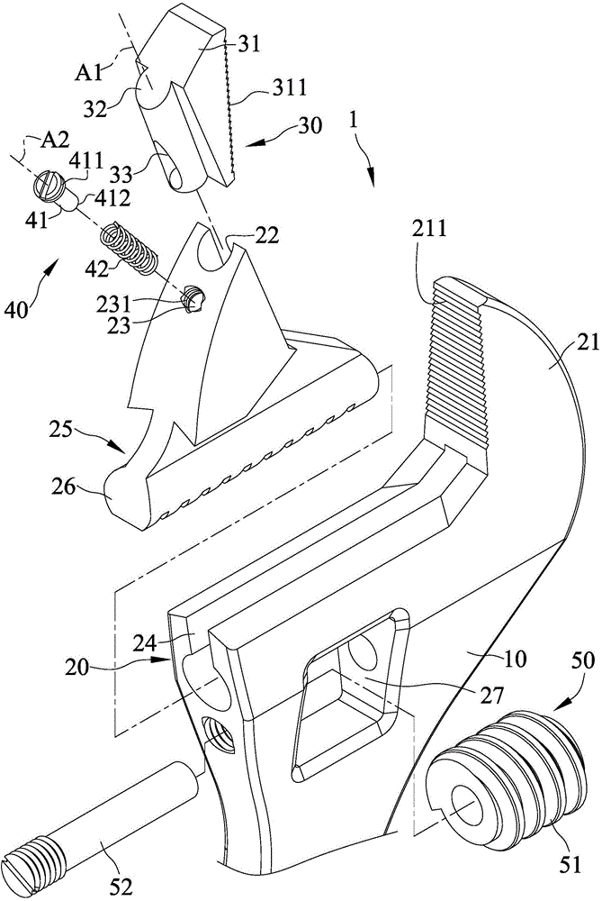
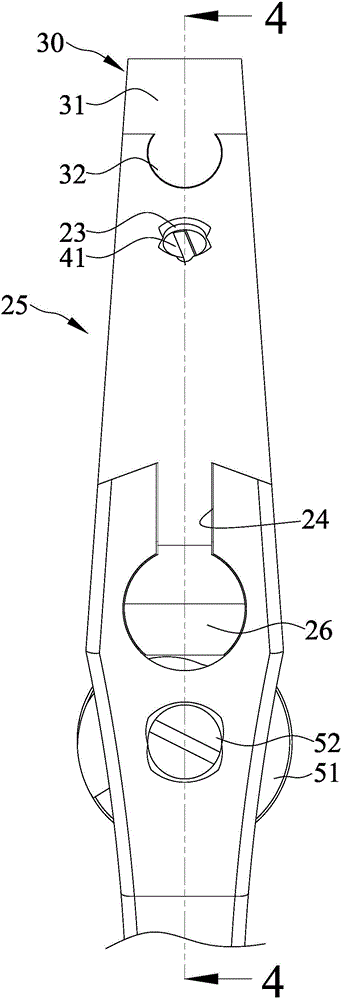
[0041] Please refer to Figure 1 to Figure 6 , Which are a partial three-dimensional appearance view, a partial exploded view, a side view and a cross-sectional view of the first embodiment of the ratchet wrench 1 of the present invention. The first embodiment of the ratchet wrench 1 of the present invention is an adjustable wrench, which includes a handle 10, a head 20, a movable jaw 30, a biasing device 40 and an adjusting device 50.
[0042] The handle 10 can be held by a user.
[0043] The head 20 is formed at any end of the handle 10 along a length direction. The head 20 includes at least one fixed jaw 21, a sliding groove 22, a receiving hole 23, a catch groove 24, and a movable jaw 25 , A catch 26 and a slot 27. In this embodiment, the head 20 has a fixed jaw 21, and the fixed jaw 21 has a first tooth surface 211. The sliding groove 22 communicates with the cavity 23, and the inner periphery of the cavity 23 is provided with a first tooth surface. A threaded portion 231, the detent groove 24 is formed in the head 20 along a width direction, the width direction is perpendicular to the length direction, the movable jaw 25 is slidably disposed in the detent groove 24 and can be fixed relative to the The jaw 21 moves, the sliding groove 22 is formed on an end surface of the movable jaw 25 facing the fixed jaw 21 extending along a first axis A1, and the receiving hole 23 is formed on an end surface of the movable jaw 25 extending along a second axis A2. For the arc-shaped end surface, an included angle α is formed between the first axis A1 and the second axis A2, the included angle α is less than 45 degrees, and more preferably, the included angle α is less than 30 degrees. The detent portion 26 is formed at an end of the movable jaw 25 opposite to the sliding groove 22 and is slidably disposed in the detent groove 24, the through groove 27 is communicated with the detent groove 24, and the through groove 27 penetrates the The sides of the head 20.
[0044] The movable jaw 30 includes a clamping portion 31, a connecting portion 32 and a receiving groove 33. The clamping portion 31 faces the fixed jaw 21 of the head 20. The clamping portion 31 has a second tooth surface 311, The second tooth surface 311 and the first tooth surface 211 of the fixed jaw 21 face each other, so as a fastener (in Figure 4 (Indicated by dashed lines) when clamped between the first tooth surface 211 of the fixed jaw 21 and the second tooth surface 311 of the clamping portion 31, the fastener and the fixed jaw 21 and the clamping The friction between the parts 31 improves the efficiency of rotating the fastener. The connecting portion 32 is formed along the first axis A1 on an end surface of the clamping portion 31 away from the fixed jaw 21 and is slidably disposed in the sliding groove 22 of the head 20. More preferably, the connecting portion 32 Having an approximately circular cross section, the receiving groove 33 is formed in the connecting portion 32 and communicates with the receiving hole 23 of the head 20. More preferably, the receiving groove 33 and the receiving hole 23 correspond to each other and communicate with each other. An elongated hole having a circular cross-section taken along the first axis A1 is formed.
[0045] The biasing device 40 includes a limiting member 41 and a biasing member 42, the limiting member 41 is connected to the receiving hole 23 of the head 20, and the biasing member 42 is received in the receiving hole 23 and the receiving groove 33, The opposite ends of the biasing member 42 abut against a bottom of the restricting member 41 and the recess 33 respectively. A second threaded portion 411 is provided on the outer periphery of the restricting member 41, and the first threaded portion 231 and the second threaded portion 411 of the receiving hole 23 are connected to each other. The limiting member 41 further includes an extension portion 412 extending along the second axis A2. In this embodiment, the biasing member 42 is a coil spring, and the extension portion 412 of the limiting member 41 extends through the biasing member 42. 压件42.
[0046] The adjusting device 50 is arranged in the through slot 27 of the head 20 and is locked with the locking portion 26. The adjusting device 50 includes a worm wheel 51 and a rod 52. The worm wheel 51 is rotatably disposed in the through slot 27 and meshes with the latch 26. In this way, rotating the worm wheel 51 can drive the movable jaw 25 to The detent groove 24 moves relative to the fixed jaw 21 to adjust the distance between the fixed jaw 21 and the clamping portion 31, so that the ratchet wrench 1 has the function of an adjustable wrench to meet a variety of different sizes of fastening Pieces. The rod 52 penetrates the worm wheel 51 and is connected to an inner wall surface of the through slot 27.
[0047] Please also refer to Figure 7 versus Figure 8 , Which is a schematic diagram of the use of the first embodiment of the ratchet wrench 1 of the present invention. When the two opposite clamping surfaces of the fastener are respectively clamped between the first tooth surface 211 of the fixed jaw 21 and the second tooth surface 311 of the clamping portion 31, and the user holds the handle 10 Pull the fastener along a driving direction, and the fastener gives a horizontal component of force to the clamping portion 31 of the movable jaw 30. The movable jaw 30 is positioned in the sliding groove 22 without slipping, so that the fastener Driven by the ratchet wrench 1.
[0048] When the user holds the handle 10 and pulls the fastener in a release direction opposite to the driving direction, the movable jaw 30 slides along the first axis A1 relative to the sliding groove 22, resulting in the biasing device 40 The biasing member 42 is elastically compressed between the bottom of the receiving groove 33 and the restricting member 41, so that the fastener cannot be driven by the ratchet wrench 1, thus achieving the effect of ratcheting.
[0049] Please refer to Picture 9 versus Picture 10 , Which are a partial three-dimensional external view and a cross-sectional view of the second embodiment of the ratchet wrench 1a of the present invention. The second embodiment of the ratchet wrench 1a of the present invention is an open-end wrench, which includes a handle 10a, a head 20a, a movable jaw 30a and a biasing device 40a.
[0050] The handle 10a can be held by a user.
[0051] The head 20a is formed at any end of the handle 10a along a length direction, and the head 20a includes at least one fixed jaw 21a, a sliding groove 22a, and a receiving hole 23a. In this embodiment, the head 20a includes two fixed jaws 21a, the sliding groove 22a communicates with the containing hole 23a, and the sliding groove 22a and the containing hole 23a are respectively along a first axis A1 and a second axis A2. Extending and forming on one of the two fixed jaws 21a, an included angle α is formed between the first axis A1 and the second axis A2, the included angle α is less than 45 degrees, more preferably, the included angle α is less than 30 degrees . The other fixed jaw 21a has a first tooth surface 211a, and a first threaded portion 231a is provided on the inner periphery of the receiving hole 23a.
[0052] The movable jaw 30a includes a clamping portion 31a, a connecting portion 32a and a receiving groove 33a, the clamping portion 31a faces the fixed jaw 21a of the head 20a, and the clamping portion 31a has a second tooth surface 311a, The second tooth surface 311a and the first tooth surface 211a of the fixed jaw 21a face each other, so as a fastener (in Figure 8 (Indicated by a dashed line) when clamped between the first tooth surface 211a of the fixed jaw 21a and the second tooth surface 311a of the clamping portion 31a, the fastener and the fixed jaw 21a and the clamping The friction between the parts 31a improves the efficiency of rotating the fastener. The connecting portion 32a is formed along the first axis A1 on an end surface of the clamping portion 31a away from the fixed jaw 21a and is slidably disposed in the sliding groove 22a of the head 20a. More preferably, the connecting portion 32a Having an approximately circular cross-section, the receiving groove 33a is formed in the connecting portion 32a and communicates with the receiving hole 23a of the head 20a. More preferably, the receiving groove 33a and the receiving hole 23a correspond to each other and communicate with each other. An elongated hole having a circular cross-section taken along the first axis A1 is formed.
[0053] The biasing device 40a includes a limiting member 41a and a biasing member 42a, the limiting member 41a is connected to the receiving hole 23a of the head 20a, and the biasing member 42a is received in the receiving hole 23a and the receiving groove 33a, The opposite ends of the biasing member 42a respectively abut against a bottom of the restricting member 41a and the recess 33a. A second threaded portion 411a is provided on the outer periphery of the restricting member 41a, and the first threaded portion 231a of the receiving hole 23a and the second threaded portion 411a are connected to each other. The limiting member 41a further includes an extension portion 412a extending along the second axis A2. In this embodiment, the biasing member 42a is a coil spring, and the extension portion 412a of the limiting member 41a extends through the biasing member 42a. 压件42a.
[0054] Please refer to Picture 11 , Which is a partial view of the third embodiment of the ratchet wrench of the present invention. The third embodiment of the ratchet wrench of the present invention is substantially the same as the first embodiment. The only difference is that the movable jaw 25 includes a first connecting section 251 and a second connecting section 252. The first connecting section 251 and the second connecting section 251 The two connecting sections 252 are integrally formed along the length direction. The first connecting section 251 has a first thickness T1. The second connecting section 252 is adjacent to the latching portion 26 and has a second thickness T2, the second thickness T2 being greater than The first thickness T1. In this way, the structural strength of the movable jaw 25 is improved, and can withstand the torsion force of the rotating fastener.
[0055] In summary, the ratchet wrench 1, 1a of the present invention has the following advantages:
[0056] 1. The ratchet wrench 1, 1a of the present invention has a simple structure and is easy to assemble, which greatly reduces the manufacturing cost and provides the effect of ratcheting.
[0057] 2. When the fastener is clamped between the first tooth surface 211 of the fixed jaw 21 and the second tooth surface 311 of the clamping portion 31, and the user holds the handle 10 to pull in a driving direction Move the fastener, the fastener gives a horizontal component of force to the clamping portion 31 of the movable jaw 30, and the movable jaw 30 is positioned in the sliding groove 22 without slipping, so that the fastener is subjected to the ratchet wrench 1 drive. When the user holds the handle 10 and pulls the fastener in a release direction opposite to the driving direction, the movable jaw 30 slides along the first axis A1 relative to the sliding groove 22, resulting in the biasing device 40 The biasing member 42 is compressed by the bottom of the receiving groove 33 and the restricting member 41, so that the fastener cannot be driven by the ratchet wrench 1, thus achieving the effect of ratcheting.
[0058] 3. In an embodiment of the present invention, the sliding groove 22 is formed on an end surface of the movable jaw 25 facing the fixed jaw 21 extending along the first axis A1, and the receiving hole 23 is formed extending along the second axis A2 On an arc-shaped end surface of the movable jaw 25, the included angle α is formed between the first axis A1 and the second axis A2, and in another embodiment of the present invention, the sliding groove 22a and the receiving hole 23a are respectively along The first axis A1 and the second axis A2 are extended to form one of the two fixed jaws 21a, and the included angle α is formed between the first axis A1 and the second axis A2, so that the containing holes 23, 23a and The sliding grooves 22 and 22a are separated by a certain distance and are not parallel to each other. In this way, the movable jaw 25 or one of the two fixed jaws 21a can have a higher structural strength.
[0059] 4. The pockets 33, 33a are formed on the connecting portions 32, 32a of the movable jaws 30, 30a and communicate with the pockets 23, 23a of the heads 20, 20a, so that the pockets 33, 33a do not need to penetrate the The two ends of the movable jaws 30 and 30a enable the movable jaws 30 and 30a to have higher structural strength.
[0060] 5. The movable jaw 25 includes a first connecting section 251 and a second connecting section 252. The first connecting section 251 and the second connecting section 252 are integrally formed along the length direction. The first connecting section 251 has a first connecting section 251. A thickness T1, the second connecting section 252 is adjacent to the catch 26 and has a second thickness T2, the second thickness T2 is greater than the first thickness T1. In this way, the structural strength of the movable jaw 25 is improved, and can withstand the torsion force of the rotating fastener.
[0061] The above description is only illustrative rather than restrictive for the present invention. Those skilled in the art understand that many modifications, changes or equivalents can be made without departing from the spirit and scope defined by the claims, but All will fall within the protection scope of the present invention.