Laminating technology employing latticed adhesive

An adhesive, grid technology, used in adhesives, lamination, lamination devices, etc., can solve problems such as invisible

Active Publication Date: 2015-07-29
胶王公司
View PDF5 Cites 7 Cited by
  • Summary
  • Abstract
  • Description
  • Claims
  • Application Information

AI Technical Summary

Problems solved by technology

This leads to the formation of visible and invisible cracks in the finished laminate molded part

Method used


Image

  • Laminating technology employing latticed adhesive
  • Laminating technology employing latticed adhesive

Examples


Embodiment

[0113] Unless otherwise specified, all measurements and test parameters were performed under standard conditions familiar to those skilled in the art, ie at room temperature (21°C + / - 1°C) and atmospheric pressure (1 atm).

[0114] In the following experiments, a non-reactive polyolefin-based hot melt adhesive from Jowat AG, Germany ( 238.30).

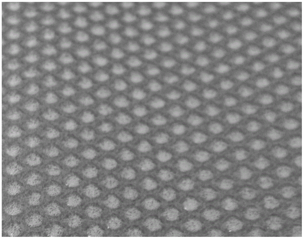
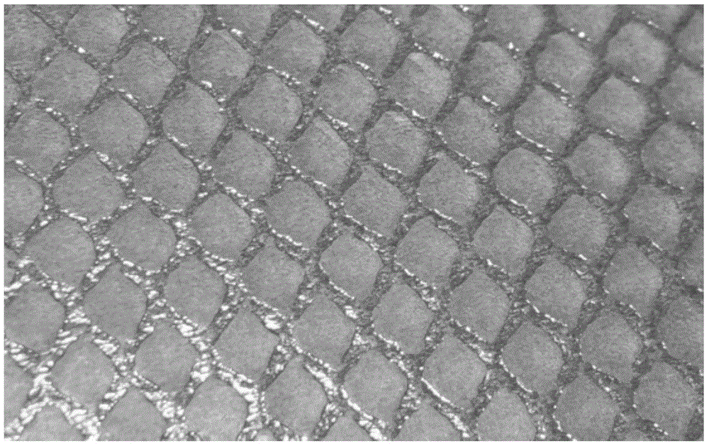
[0115] The adhesive was applied to the bottom side of a TPO sheet (Benecke-Kaliko / Germany, 2 mm foam with 0.8 mm cover layer) by means of a gravure printing roller, available from the company Hardo (Germany).

[0116] An untextured disc-shaped element (240 mm diameter, 50 mm depth) made of polyoxymethylene (POM) with vacuum holes at the periphery at about 2 cm intervals was used with a single-position vacuum layer using a coated sheet Lamination was carried out using a pressing system from the company Kiefel (Germany) in which the bottom side of the sheet was heated at 180° C. and the top side was heated at 140° C. and the sheet was ...


PUM

PropertyMeasurementUnit
thicknessaaaaaaaaaa
thicknessaaaaaaaaaa
thicknessaaaaaaaaaa

Abstract

The invention relates to a technology employing a sheet material to achieve the laminating of a part, wherein an adhesive is applied to the surface of the laminated sheet material and / or the part in a mode of grid. Therefore, the adhesive is disposed between the sheet material and the part after the sheet material and the part are bonded. Moreover, a trench system is formed in a space between the used adhesive, and guarantees that air between the part and the sheet material can move uniformly. The invention also relates to a laminated molding part made through the above technology. The latticed adhesive is used between the part and the laminated sheet material guarantees the reduction or prevention of air contents when the part and the sheet material are laminated at the same time.

Description

technical field [0001] The present invention relates to a process for laminating components with sheets, wherein an adhesive is applied to the laminated sheets and / or components in a grid pattern, whereby the adhesive is located on the sheets and components after bonding of the sheets and components The area in between and between the applied adhesive forms a groove system which ensures that the air present between the element and the sheet can be moved (extracted) evenly due to the reduced pressure. [0002] The invention also relates to a laminated molded part obtainable by the process described above. The use of an adhesive grid between the element and the laminate ensures that air inclusions are reduced or prevented when the element and laminate are laminated together. Background technique [0003] It is common in industry to laminate components, such as the in-mold embossing (IMG) method, and / or apply a pressing force by applying reduced pressure or vacuum, such as vac...

Claims


Application Information

Patent Timeline
Patent Type & Authority Applications(China)
IPC IPC(8): B32B37/12B32B27/08
CPCB32B2605/00B32B37/003B32B37/1292B29C63/0047B29C2063/485C09J5/00C09J2400/226B32B27/20B32B27/304B32B27/308B32B27/365B32B27/40B32B2262/101B32B2262/106B32B7/14B32B27/08B32B27/285B32B27/32B32B37/1018B32B37/18B32B2355/00C09J2301/204B29C65/4815B29C65/52B29K2655/00B29K2671/02B32B37/06B32B2250/02B32B2371/00
Inventor 托马斯·霍贝格
Owner 胶王公司
Why Eureka
Try Eureka