Roller member, sheet feeder and image forming apparatus

一种输送装置、辊部件的技术,应用在片材输送装置以及图像形成装置领域,能够解决片材偏移、更换需要时间、成本上升等问题,达到简单结构的效果

Active Publication Date: 2015-07-29
KONICA MINOLTA INC
View PDF10 Cites 2 Cited by
  • Summary
  • Abstract
  • Description
  • Claims
  • Application Information

AI Technical Summary

Problems solved by technology

[0006] However, there is a problem that the roller is attached to the outer periphery of the rotating shaft only by engaging the snap-fit ​​claws provided on the inside of the core material of the roller with the grooves provided on the outer periphery of the rotating shaft as described above. There is a gap between the snap-fitting claw and the groove, and as a result, the roller attached to the rotating shaft becomes loose, and when a sheet of recording paper or the like is fed and conveyed from a paper feeder, etc., the sheet deviates, causing a paper feed failure.
[0008] However, if the guide cover is provided on one end side of the roller portion in this way, the number of components increases and the cost increases, and a space for installing the guide cover is required, thereby increasing the size of the device. Turning away from the roller part separates the roller part from the rotating shaft. In addition, after attaching the roller part to the rotating shaft, it is necessary to rotate the guide cover toward the roller part. The operation of replacing the roller part is cumbersome and time-consuming. And other issues

Method used


Image

  • Roller member, sheet feeder and image forming apparatus
  • Roller member, sheet feeder and image forming apparatus
  • Roller member, sheet feeder and image forming apparatus

Examples


Embodiment Construction

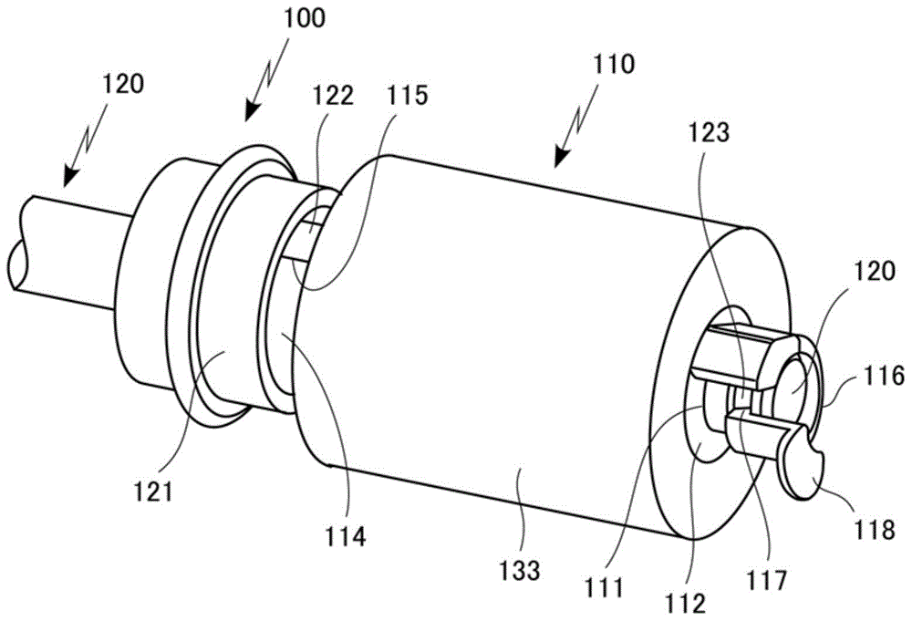
[0062] Hereinafter, a roller member, a sheet conveying device, and an image forming apparatus according to embodiments of the present invention will be specifically described based on the drawings. In addition, the roller member, the sheet conveyance device, and the image forming apparatus of the present invention are not limited to those shown in the following embodiments, and can be appropriately changed and implemented within a range that does not change the gist.

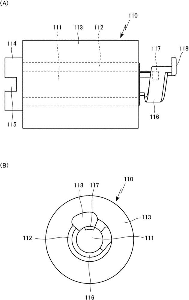
[0063] In the roller member 100 of this embodiment, as figure 1 As shown, the rotation shaft 120 is inserted through the through hole 111 of the roller portion 110 , and the roller portion 110 is detachably attached to the outer periphery of one end side of the rotation shaft 120 .

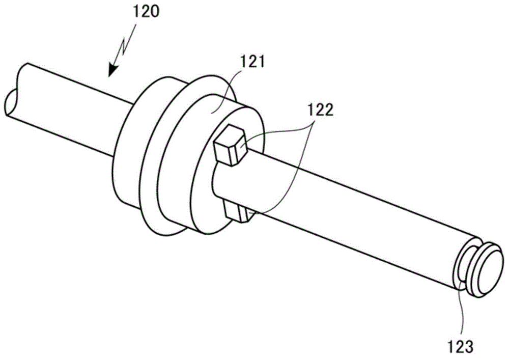
[0064] Here, in the rotating shaft 120, as figure 2 As shown, when the rotating shaft 120 is inserted through the through hole 111 of the roller part 110, the positioning holding part 121 for positioning and holding the one end si...


PUM


Abstract

In a roller member where a rotary shaft (110) is inserted through a through-hole (111) of a roller part so that the roller part is removably mounted on the rotary shaft, the rotary shaft is provided with a positioning retention part (121) for retaining one end of the roller part. Further, the rotary shaft is provided with an engagement recess (123) at place on its portion outward of the other end of the roller part. An engagement protrusion (117) is provided at a snap fit portion (116) extended axially outward from the other end of the roller part. In a state where the snap fit portion is elastically deformed in a direction opposite to the extension direction, the engagement protrusion is engaged with the engagement recess.

Description

technical field [0001] The present invention relates to a roller member for conveying a sheet or the like, a sheet conveying device and an image forming apparatus using the roller member. In particular, in the roller member in which the rotating shaft is inserted through the through hole of the roller portion and the roller portion is detachably mounted on the outer periphery of the rotating shaft, the position of the roller portion mounted on the outer periphery of the rotating shaft will not be shifted, and the roller portion will be fixed. It is characterized by being properly held at a predetermined position on the axis of rotation. Background technique [0002] Conventionally, in image forming apparatuses such as copiers and printers, a sheet conveying device that conveys a sheet of recording paper or the like from a paper feed cassette or the like has been used that conveys the sheet using a rotating roller member. [0003] In addition, as the above-mentioned roller m...

Claims


Application Information

Patent Timeline
Patent Type & Authority Applications(China)
IPC IPC(8): B65H3/06B65H5/06
CPCB65H2801/06B65H27/00B65H2404/13421B65H3/0638B65H5/06B65H2402/5152B65H29/20B65H3/5261B65H2404/1342B65H2404/134B65H2402/51
Inventor 土信田雄贵木村明夫
Owner KONICA MINOLTA INC
Why Eureka
Try Eureka