
Communication tower capable of realizing self power generation

A communication tower and self-generating technology, applied in the field of communication towers, can solve problems such as long construction period, energy consumption, and difficult site selection, and achieve the effect of solving large area, long construction period, and difficult site selection

Active Publication Date: 2015-07-29
杨再维
View PDF8 Cites 1 Cited by
  • Summary
  • Abstract
  • Description
  • Claims
  • Application Information

AI Technical Summary

Problems solved by technology

[0002] Nowadays, traditional communication towers are usually used to build sites, but the sites have the disadvantages of large area, difficult site selection, long construction period, and high cost, making it increasingly difficult to meet the needs of communication operators for rapid site construction.
Based on this, someone invented a fast integrated communication device, which includes a communication machine room and a lifting tower. Most of the existing communication tower lifting devices are motor lifting, hydraulic cylinder lifting and pulley block lifting, etc., but the structure of the above lifting device is complicated. The structure of the tower is not firm, and the lifting device and communication device in it all need electric energy supply, which consumes energy

Method used


Image

  • Communication tower capable of realizing self power generation
  • Communication tower capable of realizing self power generation
  • Communication tower capable of realizing self power generation

Examples


Embodiment Construction

[0019] The following will clearly and completely describe the technical solutions in the embodiments of the present invention with reference to the accompanying drawings in the embodiments of the present invention. Obviously, the described embodiments are only some, not all, embodiments of the present invention. Based on the embodiments of the present invention, all other embodiments obtained by persons of ordinary skill in the art without making creative efforts belong to the protection scope of the present invention.

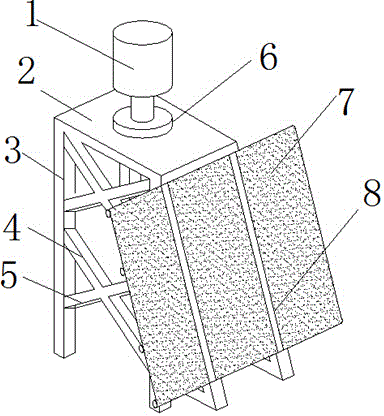
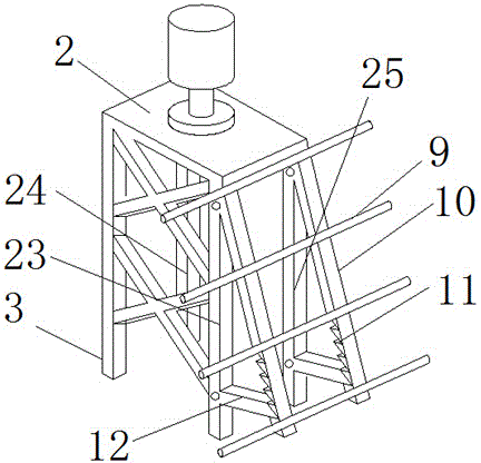
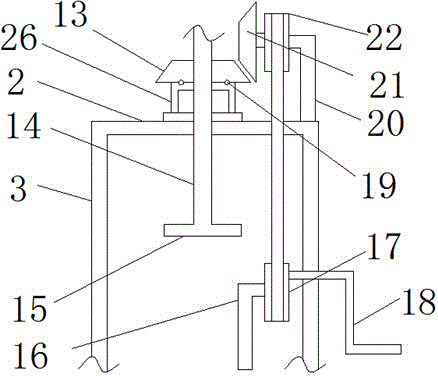
[0020] see Figure 1-3 , the present invention provides a technical solution: a communication tower capable of self-power generation, including a communication device 1, an installation platform 2 and a bracket 3, the bottom of the installation platform 2 is provided with a bracket 3, a bracket 23, and a bracket 24 And support four 25, and in the middle part of mounting platform 2, be provided with lead screw 14, the top of lead screw 14 is provided with commu...


PUM


Abstract

The invention discloses a communication tower capable of realizing self power generation. The communication tower comprises communication equipment, an installation platform and supports. According to the communication tower capable of realizing the self power generation, disclosed by the invention, a main support is formed by the installation platform supported by four supports, cross-shaped reinforcing rods are arranged among the supports, thus the structure is simple, the occupied area is small, the problems of a traditional communication tower that the occupied area is large and the site selection is difficult are effectively solved, and the problems of long construction period, high manufacturing cost and the like are solved; the top parts of the supports are hinged to installation rods, a solar cell panel is arranged on the surfaces of the installation rods, the bottom parts of the supports are provided with wedge-shaped supporting plates, the wedge-shaped supporting plates are connected with V-shaped clamping grooves formed in the bottom surfaces of the installation rods, thus the wedge-shaped supporting plates can be clamped in the V-shaped clamping grooves at different positions according to needs, the illumination angle can be timely adjusted, and the problems that both a lifting device and a communication device of the traditional communication tower need the supply of electric energy, and the energy source is consumed are effectively solved.

Description

technical field [0001] The invention relates to the technical field of communication equipment, in particular to a communication tower capable of realizing self-power generation. Background technique [0002] Today, traditional communication towers are usually used to build sites. However, sites have disadvantages such as large area, difficult site selection, long construction period, and high cost. It is increasingly difficult to meet the needs of communication operators for rapid site construction. Based on this, someone invented a fast integrated communication device, which includes a communication machine room and a lifting tower. Most of the existing communication tower lifting devices are motor lifting, hydraulic cylinder lifting and pulley block lifting, etc., but the structure of the above-mentioned lifting device is complicated. The structure of the tower is not firm, and the lifting device and the communication device therein all need the supply of electric energy,...

Claims


Application Information

Patent Timeline
Patent Type & Authority Applications(China)
IPC IPC(8): E04H12/00E04D13/18
CPCY02B10/10
Inventor 王英英
Owner 杨再维
Learn More