Low-resistance buried-gate solar cell and manufacture method thereof

A technology of solar cells and manufacturing methods, which is applied in the manufacture of circuits, electrical components, and final products, can solve problems such as incompleteness, and achieve the effects of increasing the contact area, reducing the front contact resistance, and solving the contact area and electrode shading area

Active Publication Date: 2012-07-18
TRINA SOLAR CO LTD
View PDF3 Cites 13 Cited by
  • Summary
  • Abstract
  • Description
  • Claims
  • Application Information

AI Technical Summary

Problems solved by technology

The aspect ratio of the electrode can be increased to some extent by using a laser to form a groove structure where the electrode needs to be placed, but it is not thorough enough

Method used


Image

  • Low-resistance buried-gate solar cell and manufacture method thereof
  • Low-resistance buried-gate solar cell and manufacture method thereof
  • Low-resistance buried-gate solar cell and manufacture method thereof

Examples


Embodiment Construction

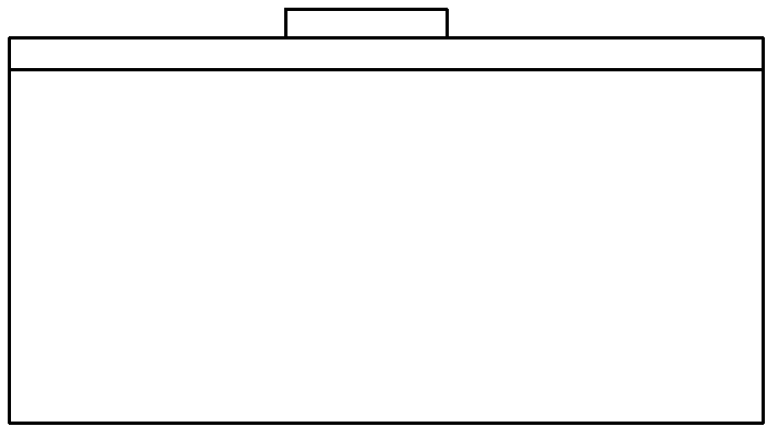
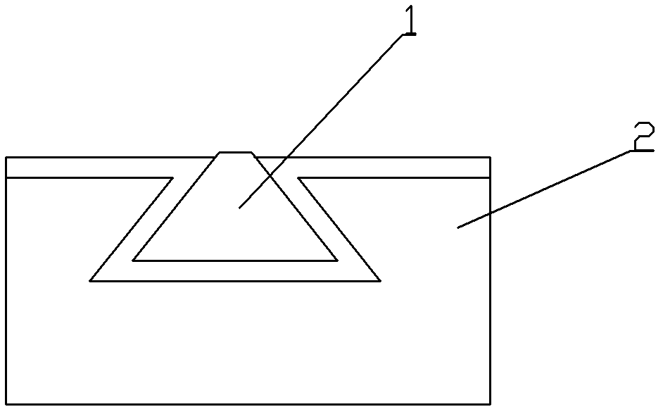
[0016] Such as figure 2 As shown, a low-resistance buried grid solar cell is provided with a front electrode on the light-receiving surface of the battery 2. On the light-receiving surface of the battery 2, a trapezoidal groove 3 with an upper narrow and a lower width is opened at the position where the front electrode needs to be arranged. A trapezoidal buried gate electrode 1 is fabricated inside.

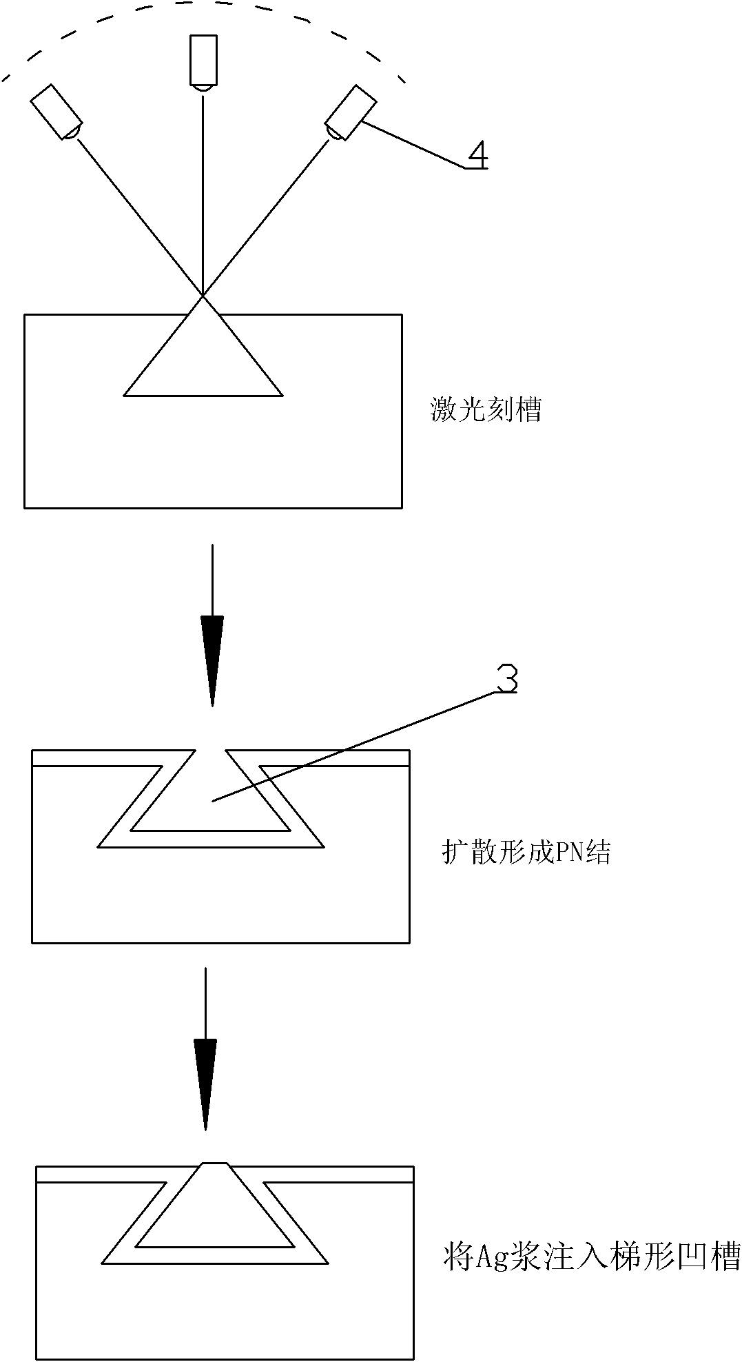
[0017] Such as image 3 As shown, the manufacturing method of the low-resistance buried grid solar cell is as follows: firstly, a trapezoidal groove 3 is made by laser grooving at the position where the trapezoidal buried gate electrode 1 needs to be formed;

[0018] The light-receiving surface forms a PN junction through a diffusion process, and the PN junction also exists in the trapezoidal groove 3;

[0019] Then use screen printing technology to inject the Ag paste into the trapezoidal groove 3;

[0020] Finally, Al paste and Ag-Al paste are printed on the back and sinter...


PUM


Abstract

The invention relates to a low-resistance buried-gate solar cell and a manufacture method of the low-resistance buried-gate solar cell. The low-resistance buried-gate solar cell is provided with a front electrode on a light-receiving surface and is provided with a trapezoidal groove with an upper narrow part and a lower wide part on a position, where the front electrode needs to be arranged, of the light-receiving surface of the cell, wherein a trapezoidal buried-gate electrode is arranged in the trapezoidal groove. The manufacture method of the low-resistance buried-gate solar cell comprises the steps of: firstly, making the trapezoidal groove on a part where the trapezoidal buried-gate electrode needs to be formed through a laser grooving method; then injecting electrode slurry in the trapezoidal groove by using a screen printing technology; and finally, forming an electrode through sintering. The low-resistance buried-gate solar cell has the beneficial effects that the contact area of the electrode and silicon is increased by adopting the trapezoidal buried-gate electrode, the contradiction between the metal electrode contact area and the electrode shielding area is eliminated, and the front contact resistance of the battery can be effectively lowered, and the filling factor and the integral efficiency are improved.

Description

technical field [0001] The invention relates to a low-resistance buried grid solar cell and a manufacturing method thereof. Background technique [0002] Such as figure 1 As shown, the current screen printing technology is equivalent to placing metal directly on the front surface of the solar cell. Since Ag is an opaque substance, the area where the electrodes exist is equivalent to being blocked from the incident light. Although the blocked semiconductor region is not completely unable to perform photoelectric conversion due to the refraction and diffraction effects of light, the blocking effect of the front electrode is still a considerable part of the efficiency loss. Therefore, the current technical improvement generally hopes to accumulate the same amount of Ag paste in the smallest possible range, that is, to increase the aspect ratio of the front electrode; this can reduce the gap between the electrode and the semiconductor while reducing the shading area. contact ...

Claims


Application Information

Patent Timeline
Patent Type & Authority Applications(China)
IPC IPC(8): H01L31/0224H01L31/18
CPCY02P70/50
Inventor 徐冠超
Owner TRINA SOLAR CO LTD
Why Eureka
Try Eureka