Constructing method of shaped field source based on metal scatterers

A construction method and scatterer technology, applied in special data processing applications, instruments, electrical digital data processing, etc., can solve problems such as excessive side lobe values, shaped field passivation, etc., to achieve elimination of side lobes, sharp The effect of simplifying the boundary and increasing the scope of application

Inactive Publication Date: 2017-10-17
UNIV OF ELECTRONICS SCI & TECH OF CHINA
View PDF2 Cites 0 Cited by
  • Summary
  • Abstract
  • Description
  • Claims
  • Application Information

AI Technical Summary

Problems solved by technology

[0006] The invention provides a method for constructing a shaped field source based on metal scatterers, which is used to solve the problems of too many side lobes, too high side lobe values, and passivation of shaped fields in electromagnetic field shaping using time inversion technology

Method used


Image

  • Constructing method of shaped field source based on metal scatterers
  • Constructing method of shaped field source based on metal scatterers
  • Constructing method of shaped field source based on metal scatterers

Examples


Embodiment 1

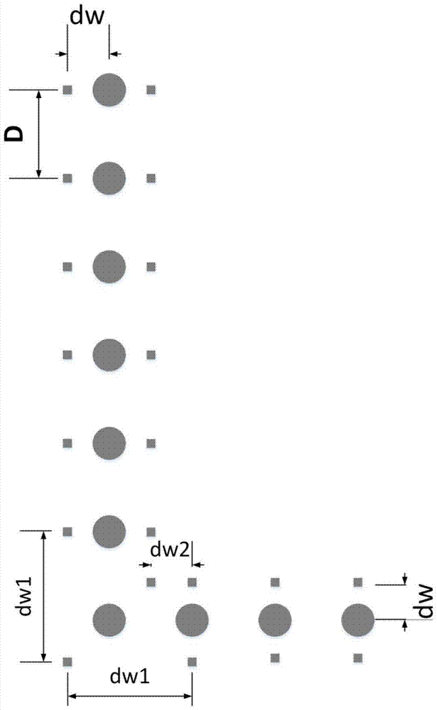
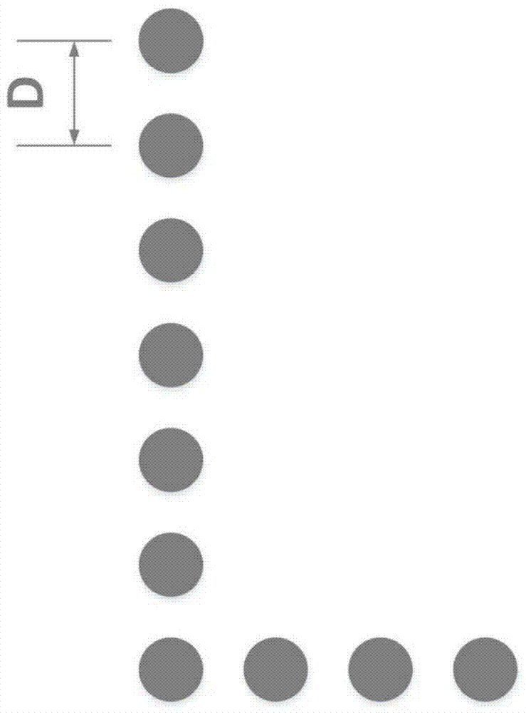
[0050] This embodiment provides a method for implementing an L-shaped shaped field source assisted by metal scatterers. First, according to step 1 of the technical solution, construct an L-shaped basic shaped field source. The specific method is to discretize the L-shaped geometry, such as image 3 As shown, the spacing D of its discrete sampling points is required to be slightly less than half a wavelength (60mm), so D=59mm in the present invention; secondly, arrange the scatterers according to the steps of the technical solution and related theories, and realize the scatterers based on metal scatterers. Shaped field source construction:

[0051] (1) Make sure that the position of the metal scatterer is around the shaped field source, such as figure 1 As shown, the distance between the metal scatterer and the shaped field source dw=0.2×D;

[0052] (2) Determine the distance between the metal scatterers themselves. The distance between most adjacent metal scatterers is the s...

Embodiment 2

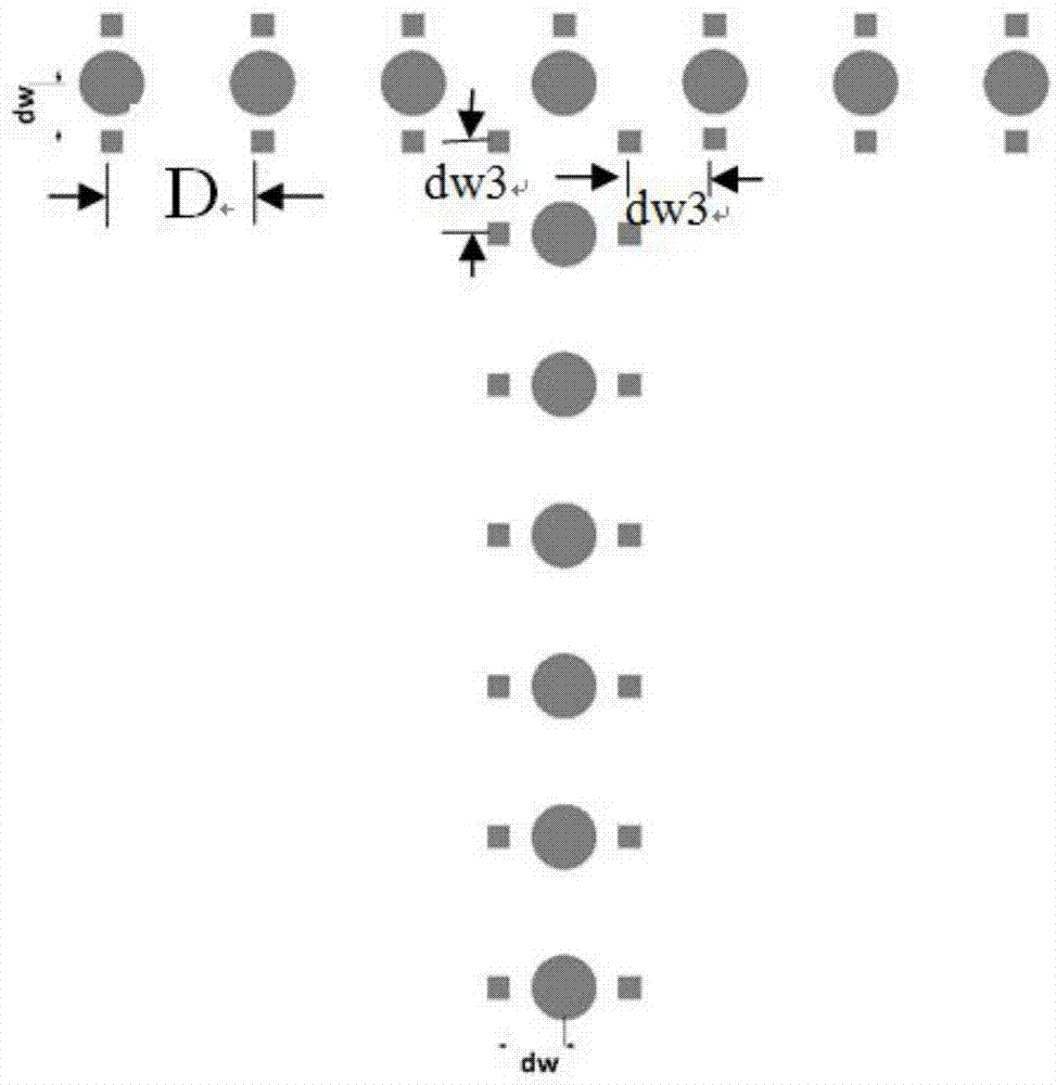
[0064] This embodiment provides an implementation method of a T-shaped shaped field source assisted by metal scatterers, which is the same as the implementation method of an L-shaped shaped field source assisted by metal scatterers. First, construct a T-shaped basic shaped field source, such as Figure 7 As shown, it is composed of 13 spatially discrete array elements, and the array element spacing is also D (59mm); secondly, the structure is based on the shaped field source assisted by metal scatterers, such as figure 2 As shown, at the position dw=0.2×D away from the basic shaped field source, the metal scatterers are arranged according to the steps of the technical solution of the present invention; the distance between most of the scatterers is D the same as the distance between the shaped field source array, and the special position is the corner According to the principle of straight line intersection, the intersection point is the spatial position of the scatterer, dw3...


PUM


Abstract

The invention provides a method for constructing a shaped field source based on the assistance of a metal scatterer, and belongs to the technical field of electromagnetic wave space propagation and control. Different from using a simple spatially discrete array to construct a shaped field source, in order to sharpen the edge field of the shaped field and reduce the problem of too many and too high side lobes outside the region, the present invention based on the random phase of the electromagnetic scattered wave in the complex medium space Based on the elimination principle, a method for constructing a shaped field source is proposed by adding a simple metal scatterer around the spatially discrete array or outside the shaped field area. This method can not only sharpen the geometric boundary of the shaped field, but also effectively solve the sidelobe problem outside the shaped field area. Difficulty in constructing high-quality shaped field sources.

Description

technical field [0001] The invention belongs to the field of space propagation and control of electromagnetic waves, and in particular relates to a method for optimizing the structure of a shaped field source in electromagnetic field shaping. Background technique [0002] The application of electromagnetic waves in the fields of communication, medical treatment, and industry has made people pay attention to and study the propagation control technology of electromagnetic waves. Antennas and their arrays, metamaterials, and circuit devices are all ways to control wave propagation, mainly through various This method controls the propagation direction of the wave, that is, the control of the pattern. With the continuous expansion of the application range of electromagnetic waves, especially in the fields of biology, medicine, chemistry, industry, etc., the research on various control problems of "wave field" has begun to attract the attention of scholars. The regeneration of th...

Claims


Application Information

Patent Timeline
Patent Type & Authority Patents(China)
IPC IPC(8): G06F17/50
Inventor 赵德双朱敏孙虎
Owner UNIV OF ELECTRONICS SCI & TECH OF CHINA
Why Eureka
Try Eureka