
A non-arc power failure protection switch control circuit

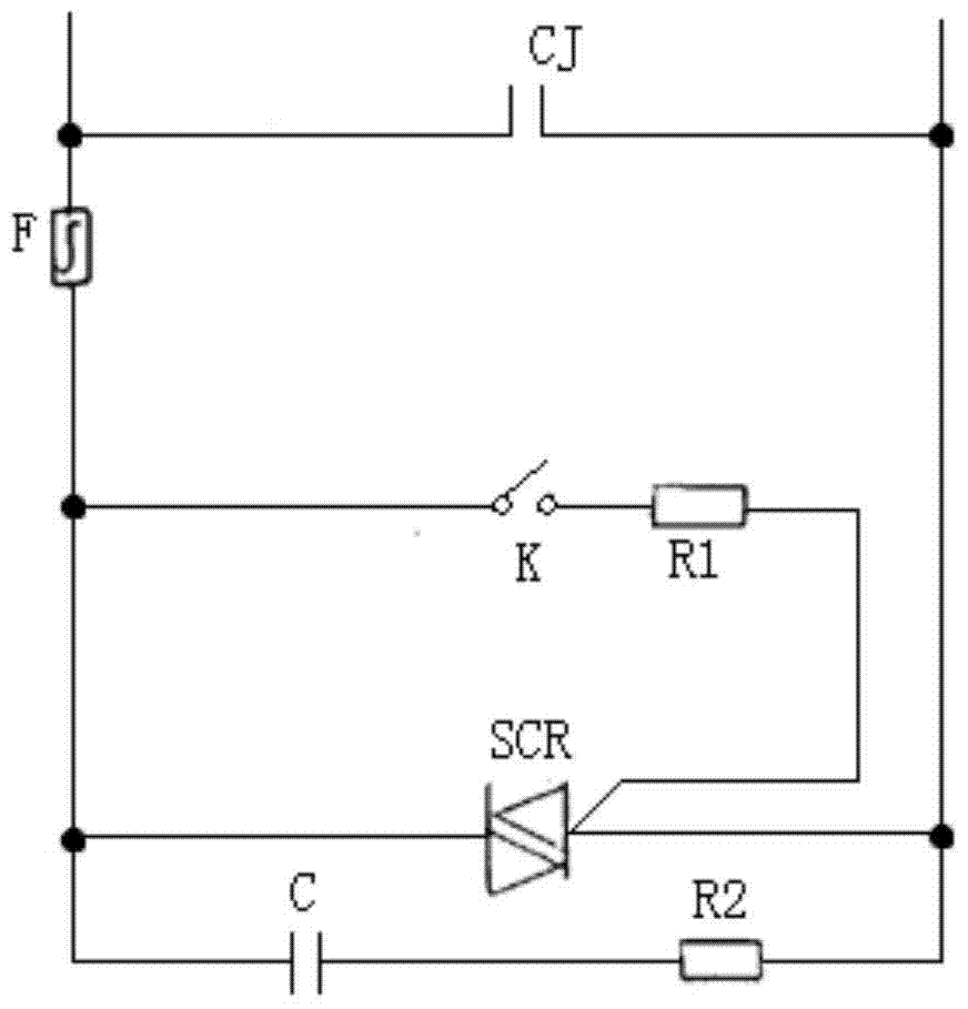
A switch control circuit, power-off protection technology, applied in the field of electrical switches, can solve the problems of long-term power-on, reduced service life, long working time, etc. impact effect

Active Publication Date: 2017-12-26
KEDU ELECTRIC CO LTD
View PDF5 Cites 0 Cited by
  • Summary
  • Abstract
  • Description
  • Claims
  • Application Information

AI Technical Summary

Problems solved by technology

Since there is a certain and uncertain value of the disconnection delay of the mechanical contactor, in order to ensure reliable disconnection without arcing, it is necessary to keep the thyristor on for a long period of time after the mechanical contacts are separated. , there is a shortcoming that the thyristor needs to be turned on for a long time when it is disconnected, resulting in a shortened service life
And the control circuit needs to be energized for a long time, and a microprocessor needs to detect the state of the switch to make correct judgments. Using this circuit to realize the function of arc-free power-off protection is costly and complicated.

Method used


Image

  • A non-arc power failure protection switch control circuit
  • A non-arc power failure protection switch control circuit
  • A non-arc power failure protection switch control circuit

Examples


Embodiment Construction

[0034] Embodiments of the present invention will be described below with reference to the drawings. It should be noted that the terms "first", "second", "third", etc. herein, if present, are used to distinguish between similar elements and do not necessarily describe a particular order or chronological order order. It is to be understood that the terms so used are interchangeable under appropriate circumstances such that the embodiments of the subject matter described herein are, for example, capable of being performed in an order different from that described herein or in another order described herein. operate. The term "connected" should be interpreted broadly and refers to electrically, mechanically, or otherwise connecting two or more elements or signals, either directly or indirectly through intermediate circuits and / or elements.

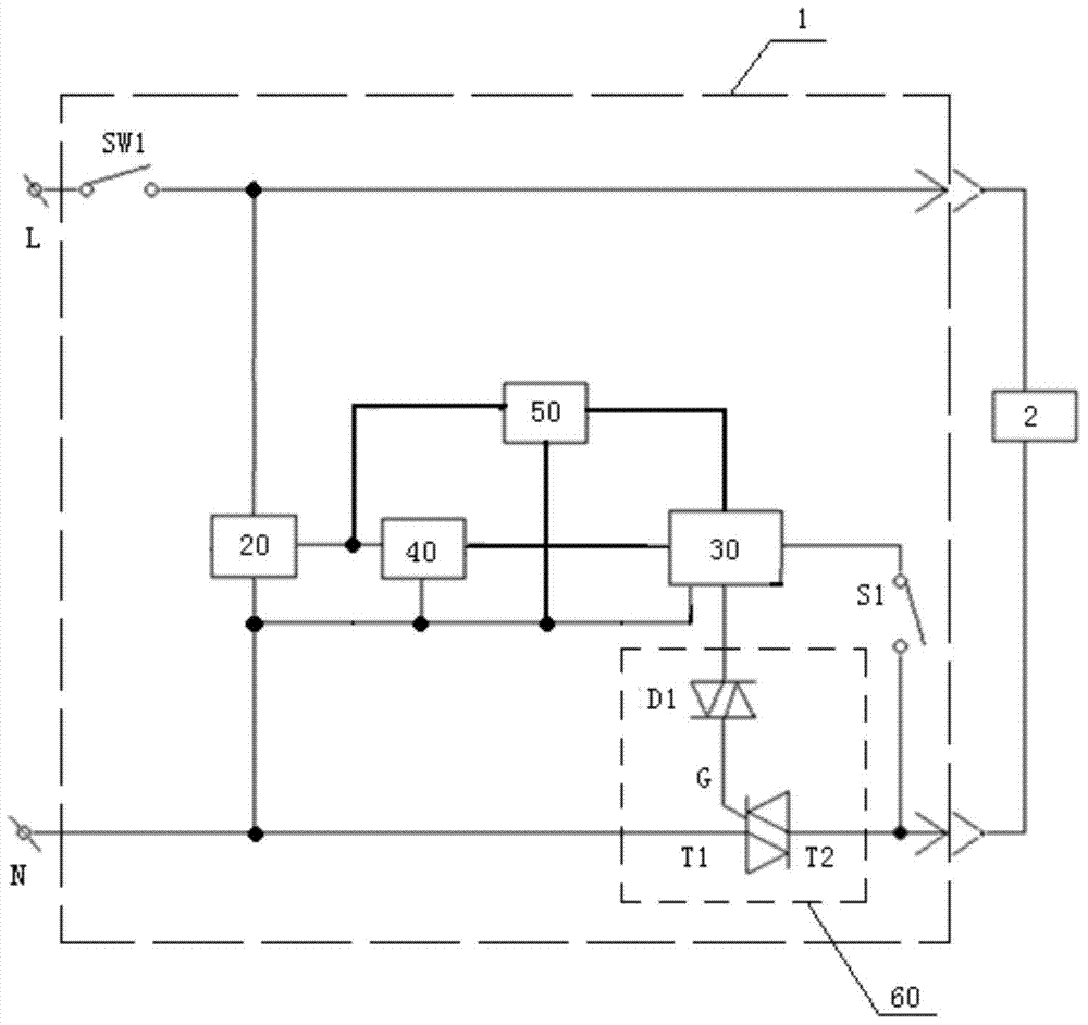
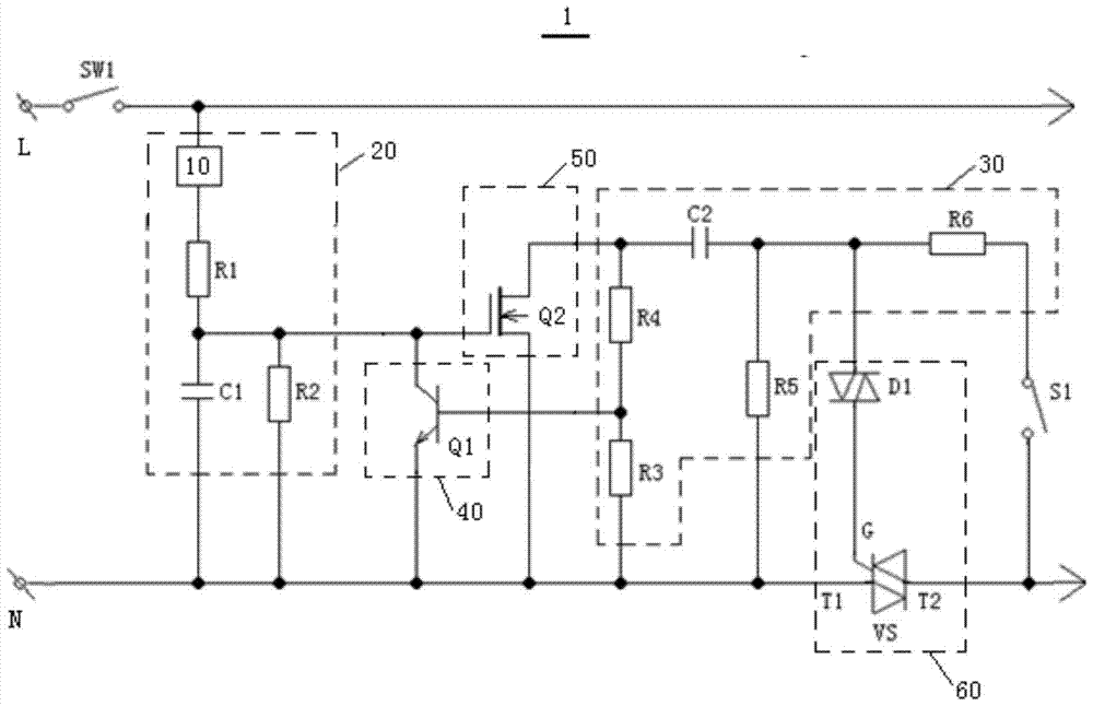
[0035] figure 2 Shows the structural block diagram of the non-arc cut-off protection switch control circuit of the embodiment of the pres...


PUM


Abstract

A control circuit for a non-arc power failure protection switch, comprising: a first switch, a second switch, a first delay circuit, a first controllable switch, a second controllable switch, a second delay circuit and a thyristor circuit; One end of the first switch is connected to the live wire of the power supply, and the other end is connected to the load; the first delay circuit is used to rectify the output of the power supply and control the on-off of the second controllable switch; the second delay circuit is used for To control the on-off of the first controllable switch, and the time constant of the second delay circuit is smaller than the time constant of the first delay circuit; the second switch is connected to the second input of the second delay circuit Between the end and the neutral line; the thyristor circuit is connected between the neutral line of the power supply and the load. The control circuit of the non-arc cut-off protection switch of the invention has the characteristics of long life, simple structure and low cost.

Description

technical field [0001] The invention belongs to the field of electric switches, and in particular relates to a control circuit for a non-arc power failure protection switch. Background technique [0002] At present, AC contactors generally use capacitors connected in parallel in the line as power factor compensation. This type of AC contactor has arcing and high surge current, and the compensation circuit is easy to break down, the service life is short, and the long-term operation cost is high. [0003] Thyristor capacitor switching switch has the advantages of no surge when connecting the capacitor and no arc when breaking the capacitor. However, due to the problems of large conduction voltage drop, temperature rise, and large harmonic pollution, it has appeared on the market for this reason. A capacitive switching switch called a compound switch with a parallel structure of a thyristor and a mechanical contact has been introduced. It has the advantages of reduced voltage ...

Claims


Application Information

Patent Timeline
Patent Type & Authority Patents(China)
IPC IPC(8): H03K17/08H03K17/72H03K17/28
Inventor 郑春开张先林李英贤张建生黄邦然李成成
Owner KEDU ELECTRIC CO LTD
Learn More