device for pressure relief

A pressure and hydraulic technology, applied in buffers, transportation and packaging, railway car body parts, etc., can solve problems such as lack

Active Publication Date: 2017-04-05
VOITH PATENT GMBH
View PDF11 Cites 0 Cited by
  • Summary
  • Abstract
  • Description
  • Claims
  • Application Information

AI Technical Summary

Problems solved by technology

In particular, there is thus a lack of solutions capable of reversibly absorbing the much higher impact forces that occur in the event of an impact accident, despite being able to reversibly absorb impacts during normal operation

Method used


Image

  • device for pressure relief
  • device for pressure relief
  • device for pressure relief

Examples


Embodiment Construction

[0047] In the following, identical or identically acting components are provided with the same reference symbols for the sake of clarity.

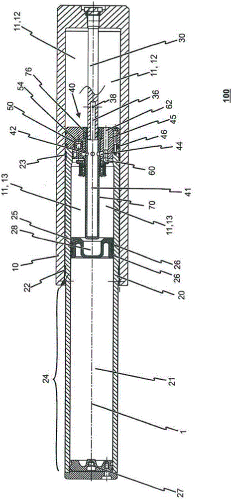
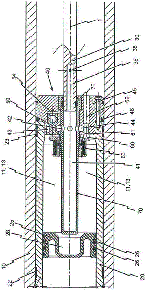
[0048] figure 1 A sectional view showing a first embodiment of a device for buffering pressure according to the present invention, said device mainly comprising a cylinder 10 and a hollow piston 20 telescopically movable along a central axis 1 in the cylinder, in which One end region of the hollow piston 20 is provided with a valve system 40 which divides the hydraulic chamber 11 formed inside the cylinder 10 into a rear hydraulic chamber region 12 and a front hydraulic chamber region 13 . The hydraulic chamber 11 thus extends at least partially into the hollow piston 20 . In other words, the front hydraulic chamber region 13 is formed inside the hollow piston 20 .

[0049] A separating piston 25 separates the front hydraulic chamber region 13 from an air chamber 21 formed inside the hollow piston 20 , wherein the air chamber 21 can be f...


PUM


Abstract

The invention relates to a device (100) for damping pressure forces in the form of an impact absorber which is designed to be reversible even in the event of dynamic impact loads. The aim of the invention is to provide a device which is designed to absorb shocks in a reliable and reversible manner during normal operation and in the event of an overload. This is achieved by a device for damping pressure forces, said device having a valve arrangement (40) with an overflow region (41) which is connected to a rear hydraulic chamber region (12) and is designed such that hydraulic fluid can flow from the rear hydraulic chamber region (12) into a front hydraulic chamber region (13). A throttle pin (30) protrudes into a connecting region between the rear hydraulic chamber region (12) and the overflow region in order to control the flow speed of the hydraulic fluid from the rear hydraulic chamber region (12) in the direction of the overflow region (41). The throttle pin (30) can be converted from a first state in which hydraulic fluid can flow from the rear hydraulic chamber region (12) into the overflow region (41) into a second state in which the rear hydraulic chamber region (12) is separated from the overflow region (41) in a fluid-tight manner. Additionally, the valve arrangement (40), which is formed at an end region of the hollow piston, has an overload valve (60) which is connected to the rear hydraulic chamber region (12) via at least one overload channel (62).

Description

technical field [0001] The invention relates to a device for damping pressure in the form of a crash safety device designed to be reversible even under dynamic crash loads. Background technique [0002] It is known from rail vehicle technology to install crash protection devices, for example in the form of so-called crash absorbers, between the individual wagons of a multi-unit vehicle. Such a component is designed in such a way that it absorbs energy in the event of a collision with a stationary or moving obstacle, for example another vehicle body, and thus prevents damage to the vehicle or the load. Such impact absorbers are mainly used in rail vehicles, in which at least one or two structural elements mounted on the end sides are used, the purpose of which is to absorb horizontal shocks acting on the rail vehicle from the outside in the longitudinal direction of the rail vehicle pressure. [0003] There are mainly two types of impact absorbers used here on rail vehicles...

Claims


Application Information

Patent Timeline
Patent Type & Authority Patents(China)
IPC IPC(8): B61G11/12F16F9/48
CPCB61G11/12F16F9/342F16F9/486
Inventor K·蒙堡C·拉德瓦根H·拉特勒
Owner VOITH PATENT GMBH
Why Eureka
Try Eureka