Passenger car engine suspension device

An engine mount and engine technology, which is applied in the power plant, jet propulsion device, internal combustion propulsion device, etc., can solve the problems of unstable engine mount structure, large vibration of the whole passenger car, poor vibration isolation effect, etc. The structure is stable, the comfort is improved, and the vibration isolation effect is good.

Inactive Publication Date: 2015-08-05
ANHUI ANKAI AUTOMOBILE
View PDF9 Cites 9 Cited by
  • Summary
  • Abstract
  • Description
  • Claims
  • Application Information

AI Technical Summary

Problems solved by technology

[0004] At present, the general-purpose engine mount adopts a simple horizontal four-point arrangement, which has a poor isolation and positioning effect on the engine, especially the isolation effect on the vertical vibration and torque vibration of the engine, and cannot isolate vibration in multiple directions, which is easy The vibration of the passenger car is relatively large, which affects the comfort of the ride
Especially for compact engines, especially when the gearbox is not allowed to be equipped with auxiliary supports, a general-purpose engine mount device is used, so that the distance between the front and rear support points of the engine is too close, the engine mount structure is unstable, and the vibration isolation effect is poor

Method used


Image

  • Passenger car engine suspension device
  • Passenger car engine suspension device
  • Passenger car engine suspension device

Examples


Embodiment Construction

[0033] A preferred embodiment of the present invention will be described in detail below with reference to the accompanying drawings.

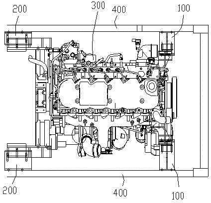
[0034] Such as figure 1 As shown, the passenger car engine suspension device adopts four-point support, including a pair of front suspension structures 100 and a pair of rear suspension structures 200, and the front suspension structures and rear suspension structures are symmetrically arranged on the left and right sides. on the frame rails. The front and rear suspension structures are all arranged at an angle of 40-50° to the plane direction where the left and right frame longitudinal beams are located, which can simultaneously isolate the vibration of the engine in six directions: up and down, left and right, and front and rear.

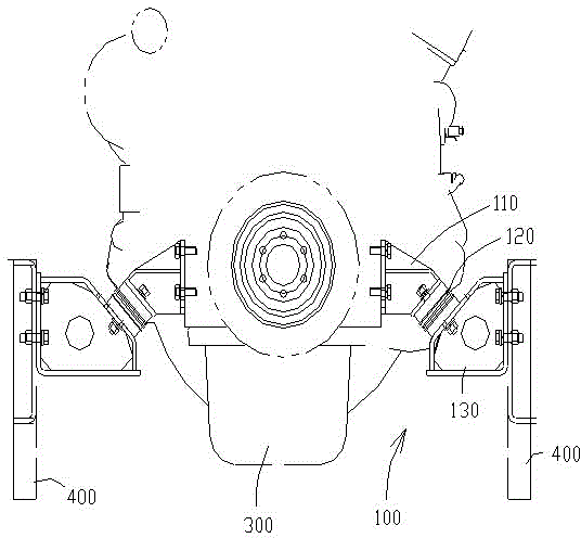
[0035] Such as figure 2 As shown, the front suspension structure 100 includes a front suspension bracket 110, a front suspension cushion 120 and a front bracket 130, the front suspension bracket is used for con...


PUM


Abstract

The invention provides a passenger car engine suspension device. The passenger car engine suspension device comprises a pair of front suspension structures and a pair of rear suspension structures. The front suspension structures and the rear suspension structures are symmetrically arranged on a left frame longitudinal beam and a right frame longitudinal beam. Each front suspension structure comprises a front suspension support, a front suspension cushion and a front bracket, wherein the front suspension support is used for being connected with an engine, the front bracket is used for being connected with the corresponding frame longitudinal beam, and the front suspension cushion is used for being connected with the front suspension support and the front bracket. Each rear suspension structure comprises a rear suspension support, a rear suspension cushion and a rear bracket, wherein the rear suspension support is used for being connected with the engine, the rear bracket is used for being connected with the corresponding frame longitudinal beam, and the rear cushion is used for being connected with the rear suspension support and the rear bracket. The included angle between each front suspension cushion and the plane where the left frame longitudinal beam and the right frame longitudinal beam are located ranges from 40 degrees to 50 degrees, and the included angle between each rear suspension cushion and the plane where the left frame longitudinal beam and the right frame longitudinal beam are located ranges from 40 degrees to 50 degrees. According to the passenger car engine suspension device, the front suspension structures and the rear suspension structures are both of an obliquely supporting structure, vibration isolation in multiple directions can be achieved, and vibration between the engine and a chassis can be effectively isolated.

Description

[0001] technical field [0002] The invention relates to the technical field of passenger cars, in particular to a passenger car engine suspension device. Background technique [0003] The engine is the power source of the passenger car, and it is also an internal vibration source, such as torque fluctuations, idling vibrations, torque changes caused by vehicle start and speed change, etc. The passenger car engine is supported and positioned by the suspension device. The suspension device can effectively prevent the transmission of engine vibration to the chassis and play the role of isolating vibration. noise transmission etc. [0004] At present, the general-purpose engine mount adopts a simple horizontal four-point arrangement, which has a poor isolation and positioning effect on the engine, especially the isolation effect on the vertical vibration and torque vibration of the engine, and cannot isolate vibration in multiple directions, which is easy Cause the whole...

Claims


Application Information

Patent Timeline
Patent Type & Authority Applications(China)
IPC IPC(8): B60K5/12
Inventor 任杰洪洋赵理想朱洪雷殷农民史先松徐凌飞周辉
Owner ANHUI ANKAI AUTOMOBILE
Why Eureka
Try Eureka