
Crankshafts for rotary compressors, rotary compressors and refrigeration cycle devices

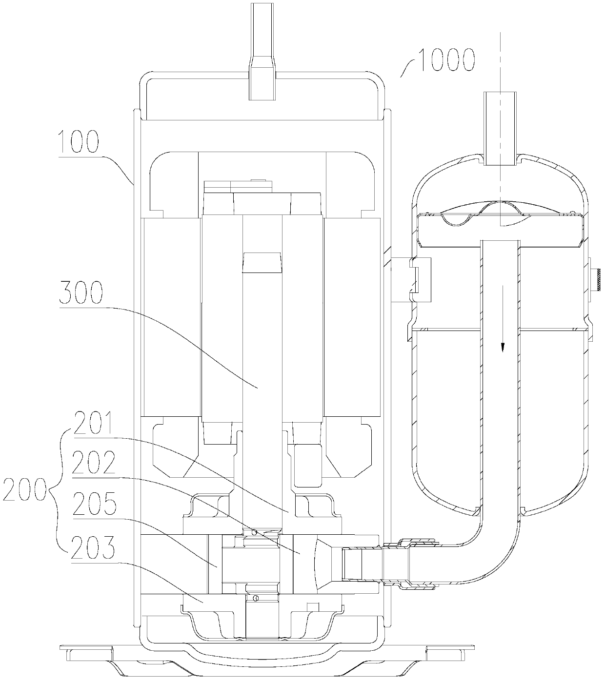
A rotary compressor and compression mechanism technology, applied in the field of compressor manufacturing, can solve problems such as poor lubrication, large friction factor, and large contact area, and achieve the effects of solving the problem of jamming, increasing the inlet oil pressure, and improving the lubrication environment.

Active Publication Date: 2018-03-20
GUANGDONG MEIZHI COMPRESSOR
View PDF6 Cites 0 Cited by
  • Summary
  • Abstract
  • Description
  • Claims
  • Application Information

AI Technical Summary

Problems solved by technology

However, if the inner diameter of the cylinder is deformed after assembly or if there are impurities in the compression mechanism, the compression mechanism will often jam at the minimum clearance, resulting in abnormal stalling of the rotary compressor
[0003] Moreover, the eccentric part of the piston and the crankshaft relies on the oil hole on the eccentric part to supply oil, so there are problems such as low oil pressure and poor lubrication. Machine input power is high

Method used


Image

  • Crankshafts for rotary compressors, rotary compressors and refrigeration cycle devices
  • Crankshafts for rotary compressors, rotary compressors and refrigeration cycle devices
  • Crankshafts for rotary compressors, rotary compressors and refrigeration cycle devices

Examples


Embodiment 1

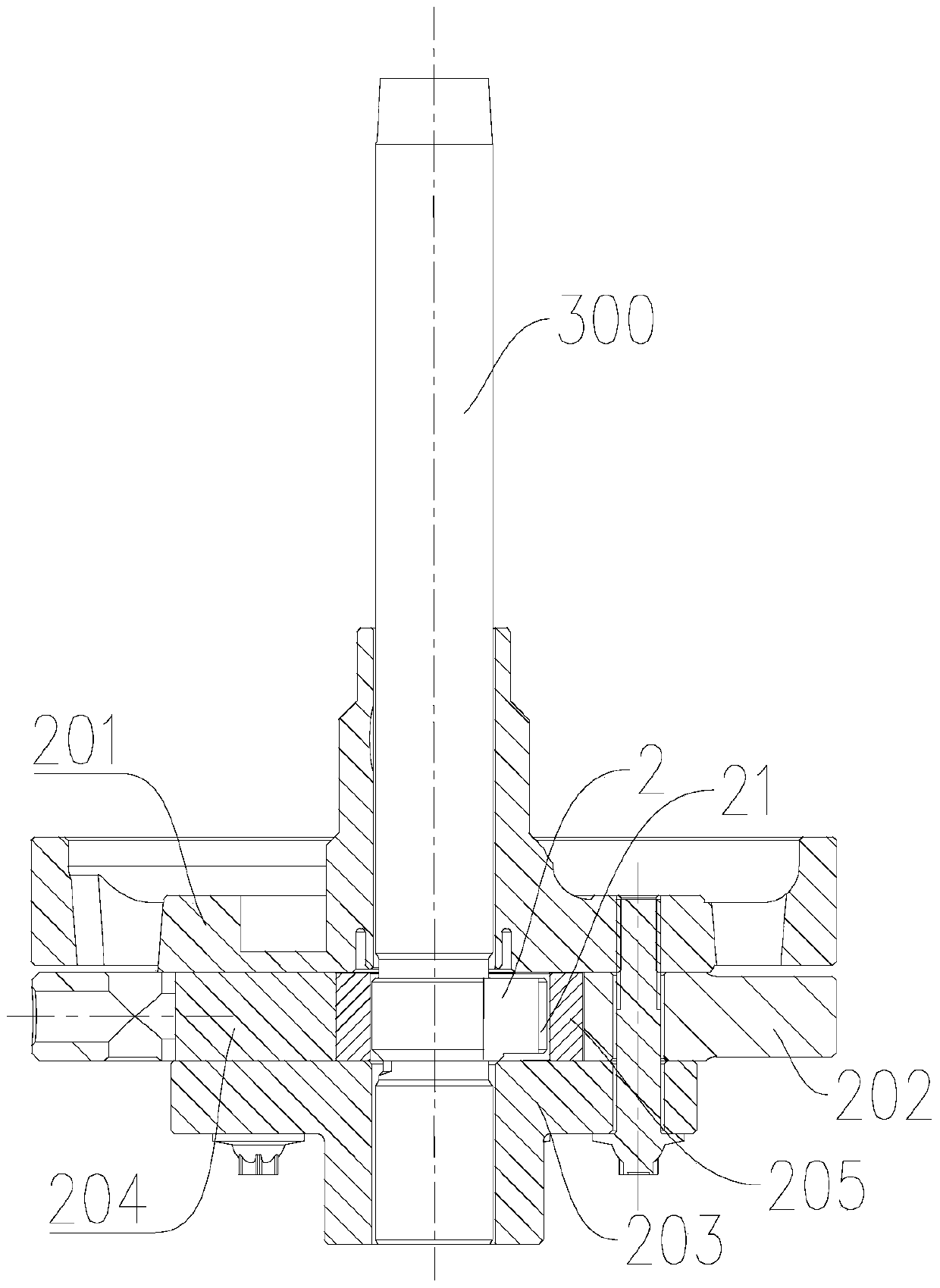
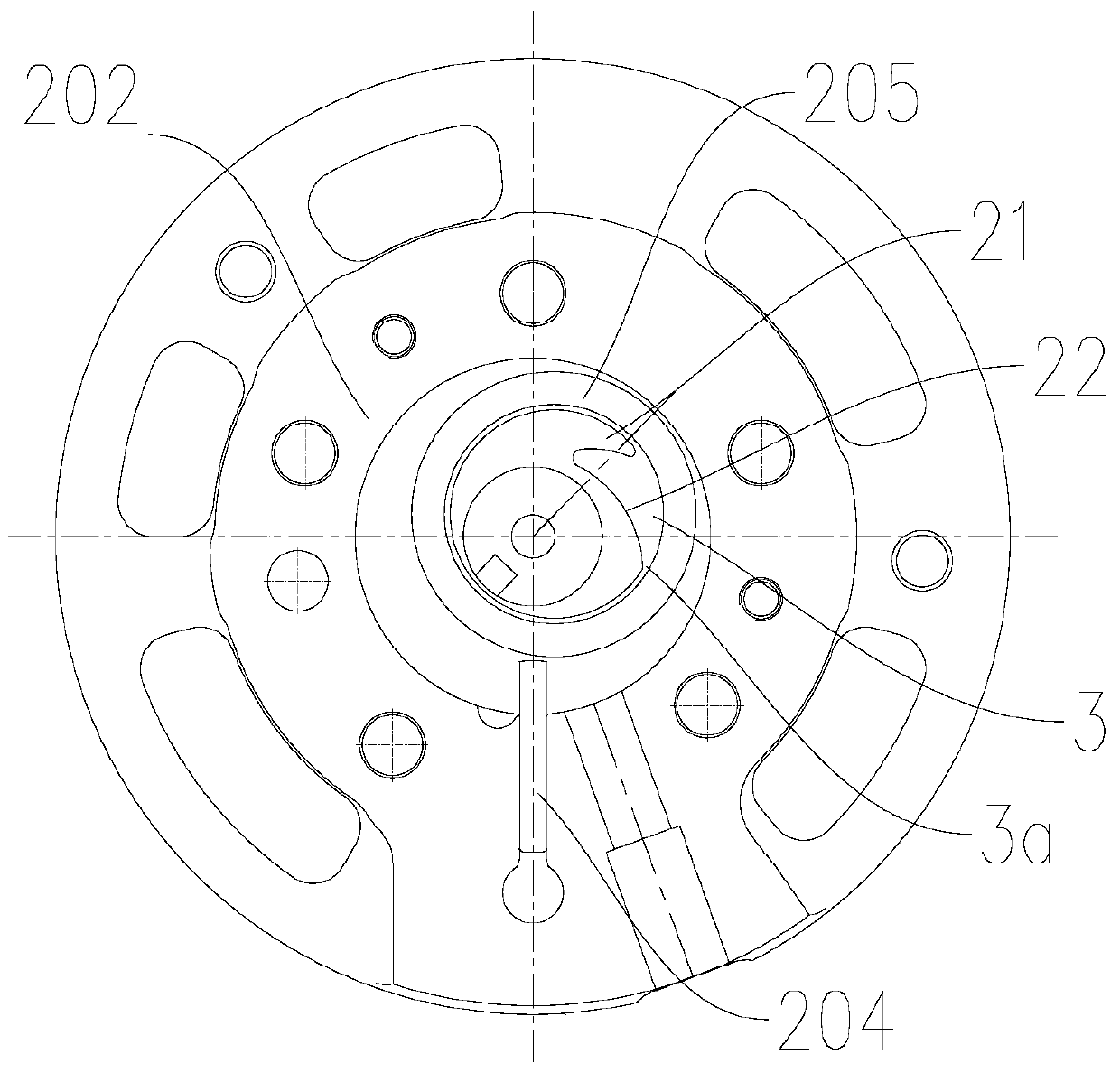
[0064] refer to Figure 7-Figure 10 , the eccentric part 2 is provided with a flexible structure 21, the flexible structure 21 has a first end 211 and a second end 212, the first end 211 of the flexible structure 21 is connected to the side wall of the eccentric part 2, and the second end of the flexible structure 21 212 and the side wall of the eccentric part 2 are spaced apart from each other. Specifically, the first end 211 of the flexible structure 21 is connected to the side wall of the eccentric part 2, and the second end 212 of the flexible structure 21 extends toward a direction away from the side wall of the eccentric part 2, so that when the piston 205 is in abnormal contact with the inner wall of the cylinder 202 At this time, the second end 212 of the flexible structure 21 can be elastically deformed to absorb the abnormal contact force, so as to improve the jamming problem of the rotary compressor 1000, and the flexible structure 21 of this structure makes the ent...

Embodiment 2

[0072] Such as Figure 11 with Figure 12 As shown, the structure of the present embodiment is substantially the same as that of the first embodiment, wherein the same components are designated with the same reference numerals, and the only difference is that no flexible structure 21 is provided on the eccentric part 2 of the third embodiment.

Embodiment 3

[0074] Such as Figure 13 with Figure 14 As shown, the eccentric part 2 is provided with a flexible structure 21, the flexible structure 21 has a first end 211 and a second end 212, and the first end 211 and the second end 212 of the flexible structure 21 are connected to the side wall of the eccentric part 2 , other parts of the flexible structure 21 except the first end 211 and the second end 212 are spaced apart from the sidewall of the eccentric part 2, at this time, a substantially A crescent-shaped cavity, and the cavity can pass through the eccentric part 2 along the axial direction of the body 1 . Thus, when the piston 205 is in abnormal contact with the inner wall of the cylinder 202, the part of the flexible structure 21 except the first end 211 and the second end 212 can be elastically deformed to absorb the contact force. Therefore, the structure of the flexible structure 21 is simple and easy to process, and the connection between the flexible structure 21 and ...


PUM


Abstract

The invention discloses a crankshaft for a rotary compressor, a rotary compressor and a refrigeration cycle device. The crankshaft comprises: a body and an eccentric part, the eccentric part is sheathed on the body, and a flexible structure is arranged on the eccentric part and at least one of the oil pressure surfaces, the flexible structure is configured to deform inwardly when subjected to an external force in an inward direction, and the oil pressure surface is configured to rotate around the rotation center axis of the crankshaft. The distance between the central axes of the parts is smaller than the distance between the tail end of the hydraulic surface and the central axis of the eccentric part. According to the crankshaft for a rotary compressor of the present invention, when the eccentric part is provided with the flexible structure of the above-mentioned structural features, it can effectively solve the problem of the rotary compressor jamming caused by the abnormal contact between the piston and the cylinder; when the eccentric When the oil pressure surface with the above-mentioned structural features is provided on the upper part, a high-pressure oil wedge can be formed at the end of the oil chamber, thereby increasing the inlet oil pressure and improving the lubrication environment between the eccentric part and the piston.

Description

technical field [0001] The invention relates to the technical field of compressor manufacturing, in particular to a crankshaft for a rotary compressor, a rotary compressor and a refrigeration cycle device. Background technique [0002] In the related art, in order to ensure the volumetric efficiency of the compression mechanism in the rotary compressor, there is usually a gap between the inner wall of the cylinder and the outer wall of the piston. However, if the inner diameter of the cylinder is deformed after assembly or there are impurities in the compression mechanism, the compression mechanism will often jam at the smallest clearance, resulting in abnormal stalling of the rotary compressor. [0003] Moreover, the eccentric part of the piston and the crankshaft relies on the oil hole on the eccentric part to supply oil, so there are problems such as low oil pressure and poor lubrication. Machine input power is high. Contents of the invention [0004] The present inve...

Claims


Application Information

Patent Timeline
Patent Type & Authority Patents(China)
IPC IPC(8): F04C29/00F04C18/356
Inventor 杨开成喻继江虞阳波
Owner GUANGDONG MEIZHI COMPRESSOR
Learn More