Supercharge Your Innovation With Domain-Expert AI Agents!

A drilling position measuring fixture

A technology for measuring fixtures and drilling positions, applied in measuring devices, mechanical measuring devices, mechanical devices, etc., can solve problems such as lack of measurement, unified, simple and accurate measurement methods, and difficult measurement, so as to achieve simple measurement, uniform distance, The effect of reducing the experimental measurement error

Inactive Publication Date: 2018-12-25
UNIV OF JINAN
View PDF6 Cites 0 Cited by
  • Summary
  • Abstract
  • Description
  • Claims
  • Application Information

AI Technical Summary

Problems solved by technology

[0003] The technical problem to be solved by the present invention is: when using a dynamometer to measure the drilling torque, there is a problem in measuring the length from the central axis of the drilling hole to the limit point of each dynamometer. Since the dynamometer itself does not have a clamp and a scale, Therefore, when measuring the drilling torque, there is no uniform, simple and accurate measurement method for measuring the length from the central axis of the drilling hole to the limit points of each dynamometer, especially when the central axis of the drilling hole is not at the same limit point as the limit points of each dynamometer. plane, measurement becomes very difficult

Method used


Image

  • A drilling position measuring fixture
  • A drilling position measuring fixture
  • A drilling position measuring fixture

Examples


Embodiment Construction

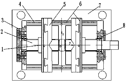
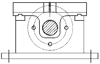
[0015] Before performing the drilling torque measurement test, firstly, the center of the fixture coordinate system is positioned to the center of the dynamometer, and the fixture is fixed on the dynamometer with bolts.

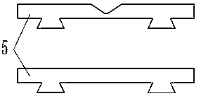
[0016] Second, determine the shape of the workpiece material, select the clamping body 5 according to the shape, and insert the clamping body 5 onto the slider.

[0017] Thirdly, place the test piece on the horizontal plate in the middle of the fixture, and clamp the workpiece by turning the two-way screw.

[0018] Fourth, when positioning the tool, use the scale 6 on the fixture to determine the position of the drilling center axis in the fixture coordinate system (that is, the coordinate value (x0, y0)).

[0019] Finally, the length of each force arm is obtained by calculation: for circular workpiece materials, the center of the test piece coincides with the center of the fixture coordinate system due to the automatic shaping function of the fixture; , the...


PUM


Abstract

When studying the drilling performance of materials, it is necessary to measure the drilling force and moment of the material, but there is no simple and accurate fixture to cooperate with the drilling moment measurement test at present. The present invention mainly designs a new type of drilling position measuring fixture. The main features of the fixture are: the center of the fixture is taken as the origin of the coordinate system, and scales are respectively engraved on the sliding guide rail and the sliding block, and the middle position is 0 point, and the left negative, positive to the right. The direct measurement of the distance from the central axis of the drilling hole to the limit point of the dynamometer is converted into the coordinate position of the central axis of the drilling hole in the fixture coordinate system, and then the distance between the limit points of each dynamometer is obtained by calculation.

Description

technical field [0001] The invention relates to a jig for measuring a drilling position in a drilling torque measurement test. Background technique [0002] At present, in the test of measuring drilling force and torque, most of them use piezoelectric force measuring instrument, but this kind of force measuring device does not have the drilling position measuring fixture matched with it, so that the drilling center axis to each There is no simple and accurate measurement method for the distance of the limit point of the dynamometer, and most of them are measured directly with a millimeter ruler. First, the determination of the measurement point is more complicated, the measurement accuracy is relatively low, and the human error is large; The length from the central axis of the hole to the limit points of each dynamometer is generally small, so a small error will also have a large impact on the measurement of the torque. In order to improve the measurement accuracy of the dr...

Claims


Application Information

Patent Timeline
Patent Type & Authority Patents(China)
IPC IPC(8): G01B5/004
Inventor 郭培全王辉乔阳牛金涛
Owner UNIV OF JINAN
Features
  • R&D
  • Intellectual Property
  • Life Sciences
  • Materials
  • Tech Scout
  • Unparalleled Data Quality
  • Higher Quality Content
  • 60% Fewer Hallucinations
Learn More