
Method for detecting ghosting effect of liquid crystal display

A liquid crystal display and detection method technology, applied in the direction of instruments, nonlinear optics, optics, etc., can solve problems such as slow response time

Inactive Publication Date: 2015-08-05
NANJING LINGYA AUTOMOBILE TECH RES INST
View PDF0 Cites 3 Cited by
  • Summary
  • Abstract
  • Description
  • Claims
  • Application Information

AI Technical Summary

Problems solved by technology

[0003] However, compared with the traditional cathode ray tube (CRT) display or the latest plasma (Plasma) display, the biggest disadvantage of liquid crystal display in use is that it has a slower response time (responsetime). caused by the structural elements of

Method used


Image

  • Method for detecting ghosting effect of liquid crystal display

Examples


Embodiment Construction

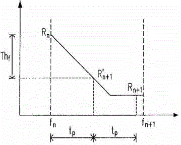
[0009] In order to improve the ghost effect, the method provided by the present invention must effectively detect and identify the pixels in the image input data that will cause the ghost effect. However, the ghosting effect is a visual phenomenon and has different changes for different observers; when a fast-moving image is presented on a liquid crystal display, two different types of effects can be observed: trail effect ) and the blinking effect. Both of these effects are caused by the slow response time of the transistor, and both can be regarded as ghost effects. The present invention provides a theory behind the reasons for these two effects, and will be guided by the theory to find out a method for detecting and identifying pixels that cause the ghost effect.


PUM


Abstract

The invention relates to a method for detecting the ghosting effect of a liquid crystal display, and the method comprises the following steps: providing human vision persistence time; providing the maximum color change speed of the liquid crystal display; calculating the product of the human vision persistence time and the maximum color change speed, so as to obtain a threshold value; calculating density level variation of a pixel element of the liquid crystal display; comparing the threshold value with the density level variation, and enabling the threshold value to be greater than the density level variation, so as to detect and eliminate the ghosting effect.

Description

technical field [0001] The invention relates to a method for detecting the ghost effect of a liquid crystal display, in particular to a thin film transistor liquid crystal display. Background technique [0002] Liquid crystal display (LCD) has been widely used in desktop computer screens, notebook computer screens, televisions and other types of display devices. With the development of its manufacturing technology, the application range of liquid crystal displays and the quality of products made It will continue to grow and develop in the future. [0003] However, compared with the traditional cathode ray tube (CRT) display or the latest plasma (Plasma) display, the biggest disadvantage of liquid crystal display in use is that it has a slower response time (responsetime). caused by the structural elements. All pixels of a liquid crystal display are produced by a color filter, and each pixel includes three sub-pixels used to generate red, green and blue, respectively, and t...

Claims


Application Information

Patent Timeline
IPC IPC(8): G02F1/13
CPCG02F1/1309
Inventor 王梦劼
Owner NANJING LINGYA AUTOMOBILE TECH RES INST
Learn More