
A method for automatic correction of non-uniformity in multi-channel ccd image mosaic

A technology of non-uniformity and image stitching, applied in image communication, color TV parts, TV system parts, etc., can solve problems such as channel unevenness, brightness and chromaticity deviation, and failure to achieve adaptive correction , to achieve the effect of simple and fast algorithm and less resources

Active Publication Date: 2016-03-23
广州烽火众智数字技术有限公司
View PDF5 Cites 0 Cited by
  • Summary
  • Abstract
  • Description
  • Claims
  • Application Information

AI Technical Summary

Problems solved by technology

[0002] At present, in the field of video processing technology, in order to obtain images and videos with higher frame rates, the CCD sensor output through 2 to 4 channels undergoes 2 to 4 channels of analog-to-digital conversion The processor collects image and video data, and the post-stage processor performs image splicing to complete the transmission function; however, in practical applications, the circuit layout and wiring methods of each channel, and the electronic components used are not completely consistent, resulting in model After digital conversion, the quantization value of each channel has a certain difference, so that there is a certain deviation in brightness and chromaticity between each channel of the spliced ​​image observed in the later stage, resulting in the image quality not reaching the expected effect
[0003]In the prior art, the method to solve this kind of phenomenon is almost to do an adjustment when the camera leaves the factory, by modifying the gain value and offset of the analog-to-digital converter However, in different scenes and different temperature environments, the inhomogeneity phenomenon between channels after image stitching will reappear, and adaptive correction cannot be achieved.

Method used


Image

  • A method for automatic correction of non-uniformity in multi-channel ccd image mosaic
  • A method for automatic correction of non-uniformity in multi-channel ccd image mosaic
  • A method for automatic correction of non-uniformity in multi-channel ccd image mosaic

Examples


Embodiment Construction

[0032] 1. System (referred to as system)

[0033] 1. Overall

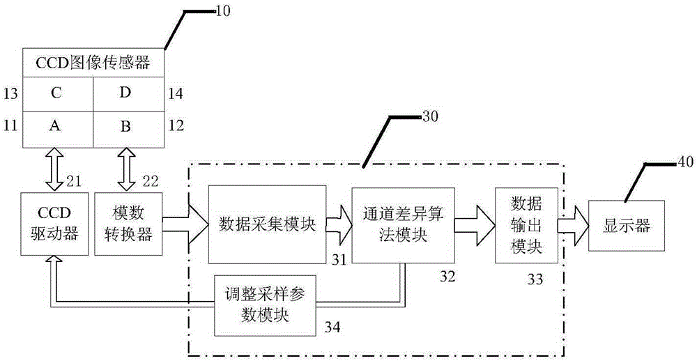
[0034] Such as figure 1 , the system includes a CCD image sensor 10, a CCD driver 21, an analog-to-digital converter 22, a processor 30 and a display 40;

[0035] Image sensor 10 includes A channel 11, B channel 12, C channel 13 and D channel 14;

[0036] The processor 30 includes a data acquisition module 31, a channel difference algorithm module 32, a data output module 33 and an adjustment sampling parameter module 34;

[0037] CCD image sensor 10, analog-to-digital converter 22, processor 30 and display 40 are connected in sequence;

[0038] The analog-to-digital converter 22, the data acquisition module 31, the channel difference algorithm module 32, the data output module 33 and the display 40 interact in sequence;

[0039] The channel difference algorithm module 32 , the sampling parameter adjustment module 34 , the CCD driver 21 and the CCD image sensor 10 interact sequentially.

[0040] 2. Functional ...


PUM


Abstract

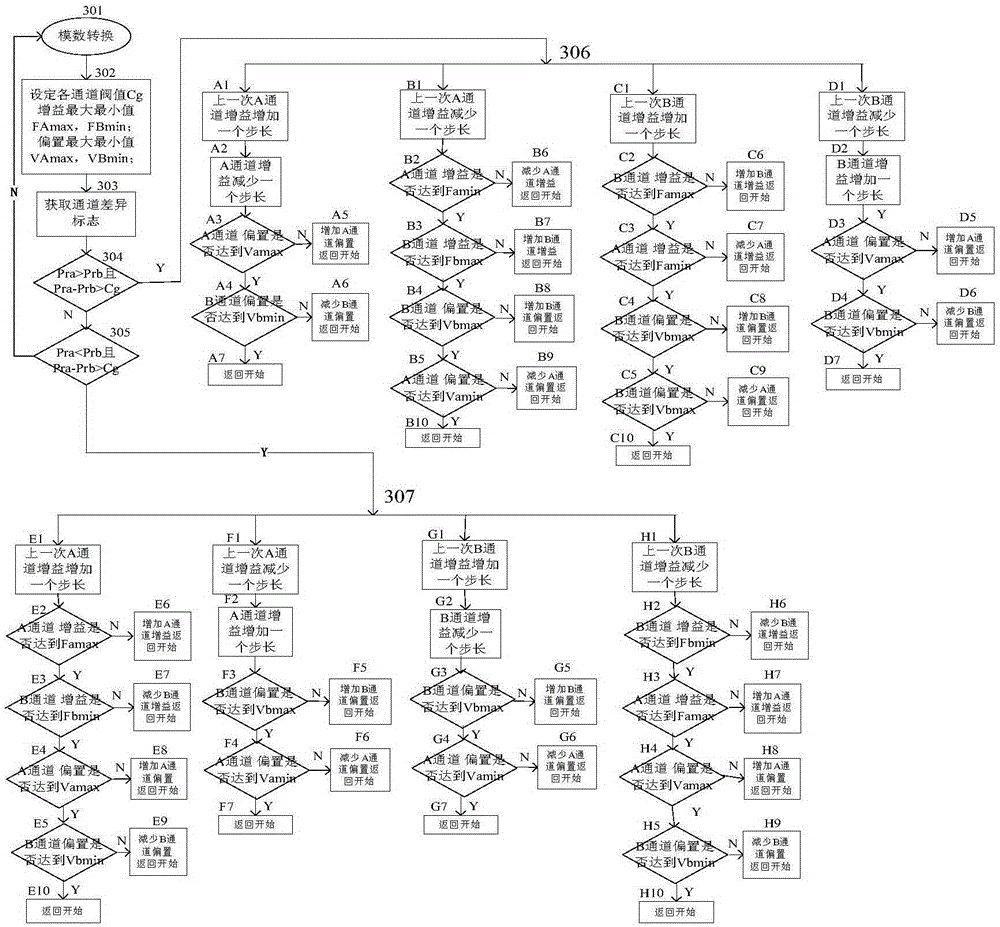
The invention discloses a multi-channel CCD image splicing non-uniformity automatic correction method, which relates to the technical field of digital image processing. This method is mainly as follows: 1. output multi-channel analog signals by photoelectric conversion of CCD sensor, and perform analog-to-digital conversion with analog-to-digital converter; 2. use any channel as a benchmark to calibrate adjacent channels; The first column and the last row of RGB three primary color data are weighted average; ④ Compare the parameters of the reference channel and the channel to be calibrated, and give back the difference sign between the channels; Non-uniformity; ⑥The floating method repeatedly adjusts the channel gain and offset parameters to make the deviation between channels infinitely small. The algorithm of the invention is simple and fast; it can well eliminate the uneven phenomenon between channels caused by multi-channel splicing; it modifies the parameter value of the analog-to-digital converter in real time to adapt to different scenes and different temperature environments.

Description

technical field [0001] The present invention relates to the technical field of digital image processing, in particular to a method for automatically correcting non-uniformity of multi-channel CCD (Charge Coupled Device) image splicing; specifically, an analog signal of a multi-channel CCD sensor undergoes multi-channel analog-to-digital conversion Finally, non-uniformity is brought about by hardware differences when the images of each channel are stitched, and the chromaticity and brightness of each channel of the stitched CCD image are consistent through automatic correction. Background technique [0002] At present, in the field of video processing technology, in order to obtain images and videos with higher frame rates, the CCD sensors output through 2 to 4 channels are used to collect image and video data through 2 to 4 analog-to-digital converters, and then processed by the subsequent processor. Image splicing completes the transmission function; however, in practical a...

Claims


Application Information

Patent Timeline
IPC IPC(8): H04N9/77H04N9/797H04N5/372
Inventor 黄庚吴超斌
Owner 广州烽火众智数字技术有限公司
Learn More