
Light foldable high-voltage switch trolley guide rail for transformer station, and use method

A high-voltage switch, trolley guide rail technology, applied in pull-out switch cabinets, switchgear, electrical components, etc., can solve the problems of loss of monitoring, heavy high-voltage switch trolley, no positioning block, etc., to avoid operation accidents and shorten operation time. , the effect of improving work efficiency

Inactive Publication Date: 2015-08-05
STATE GRID CORP OF CHINA +1
View PDF0 Cites 3 Cited by
  • Summary
  • Abstract
  • Description
  • Claims
  • Application Information

AI Technical Summary

Problems solved by technology

[0002] Nowadays, a large number of high-voltage switch cabinets are used in substations, and the high-voltage switch trolleys inside are very heavy. In order to ensure that they can bear the weight of the trolleys, the manufacturer’s supporting trolley guide rails are made of pure steel, which is heavy and has a large area. Generally, it is difficult for a single operator to move them. , bumps are prone to occur during the moving process, and there is no positioning block at the connection between the trolley guide rail and the high-voltage switch cabinet, it is difficult to completely dock, and most of them need the assistance of the guardian; there is no buffer groove at the tail of the trolley guide rail, and there is a steel plate thickness between the guide rail surface and the ground The height of the size is also difficult when the single-person trolley switch is pushed into the high-voltage switchgear, and the assistance of the guardian is also required, so that the operator will lose supervision, violate the "Electricity Safety Work Regulations", and increase the risk factor of the operation; The guide rail cannot be folded, which is not convenient for handling and occupies a large area

Method used


Image

  • Light foldable high-voltage switch trolley guide rail for transformer station, and use method
  • Light foldable high-voltage switch trolley guide rail for transformer station, and use method
  • Light foldable high-voltage switch trolley guide rail for transformer station, and use method

Examples


Embodiment Construction

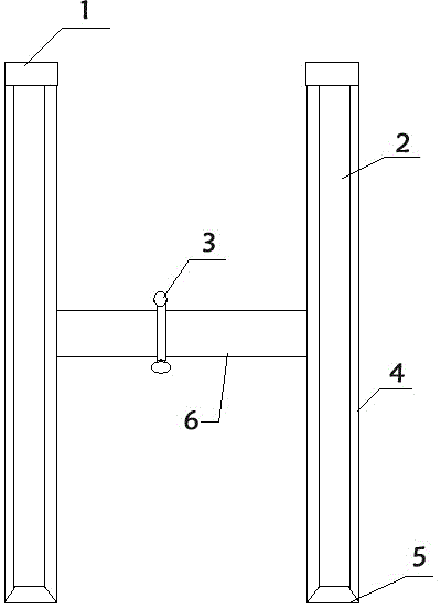
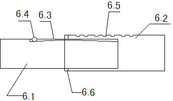
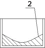
[0017] combined with Figure 1-3 , to further describe the present invention:

[0018] The present invention includes a positioning block 1, a guide rail 2, a folding shaft 3, a guide rail base 4, a buffer groove 5, and a support plate 6. Two parallel guide rail bases 4 are connected through the support plate 6. The guide rail base 4 is provided with a guide rail 2, One end of the guide rail base 4 is provided with a positioning block 1, the other end of the guide rail base 4 is provided with a buffer groove 5, and the support plate 6 is provided with a folding shaft 3; wherein, the support plate 6 includes a first support plate 6.1, a second support plate 6. The support plate 6.2, the first support plate 6.1, and the second support plate 6.2 are plugged together, the inside of the first support plate 6.1 is provided with an outer arc-shaped steel bar 6.3, and the non-arc-shaped steel bar 6.3 is provided with a semicircular groove. A ball 6.4 is provided in the semicircul...


PUM


Abstract

The invention relates to a light foldable high-voltage switch trolley guide rail for a transformer station, and a use method. According to the technical scheme of the light foldable high-voltage switch trolley guide rail, the light foldable high-voltage switch trolley guide rail comprises positioning blocks, guide rail bodies, a folding shaft, guide rail bases, buffer grooves and a support plate; and the two parallel guide rail bases are connected through the support plate, the guide rail bases are provided with the guide rail bodies, one end of each guide rail base is provided with the corresponding positioning block, the other ends of the guide rail bases are provided with the buffer grooves, and the support plate is provided with the folding shaft. The light foldable high-voltage switch trolley guide rail is advantageous in that the light foldable high-voltage switch trolley guide rail for the transformer station can help operating personnel conveniently and rapidly operate a high-voltage switch trolley, shortens operating time and improves working efficiency.

Description

technical field [0001] The invention relates to the operation of a high-voltage trolley switch in the switching operation process of a substation, in particular to a guide rail of a light-duty foldable high-voltage switch trolley in a substation and a use method thereof. Background technique [0002] Nowadays, a large number of high-voltage switch cabinets are used in substations, and the high-voltage switch trolleys inside are very heavy. In order to ensure that they can bear the weight of the trolleys, the manufacturer’s supporting trolley guide rails are made of pure steel, which is heavy and has a large area. Generally, it is difficult for a single operator to move them. , bumps are prone to occur during the moving process, and there is no positioning block at the connection between the trolley guide rail and the high-voltage switch cabinet, it is difficult to completely dock, and most of them need the assistance of the guardian; there is no buffer groove at the tail of t...

Claims


Application Information

Patent Timeline
Patent Type & Authority Applications(China)
IPC IPC(8): H02B11/127
CPCH02B11/127
Inventor 尹永亮滕维波许宏光王云涛沈亚瑞刘文卿巩天晓
Owner STATE GRID CORP OF CHINA
Learn More