Pneumatic tire

A technology for pneumatic tires and tire width directions, which is applied to pneumatic tires, tire parts, tire treads/tread patterns, etc., can solve problems such as ambiguity, and achieve excellent handling and stability effects

Active Publication Date: 2015-08-05
YOKOHAMA RUBBER CO LTD
View PDF12 Cites 12 Cited by
  • Summary
  • Abstract
  • Description
  • Claims
  • Application Information

AI Technical Summary

Problems solved by technology

It is unclear whether excellent handling stability can be achieved on dry roads, snowy roads, and slippery roads by only controlling the shape of the land portion and the ratio of the groove area as in the technology disclosed in Patent Document 1.

Method used


Image

  • Pneumatic tire
  • Pneumatic tire
  • Pneumatic tire

Examples


Embodiment Construction

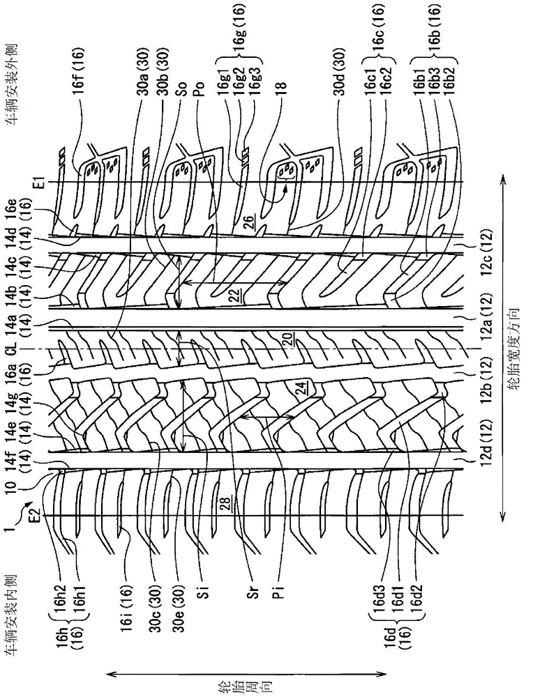
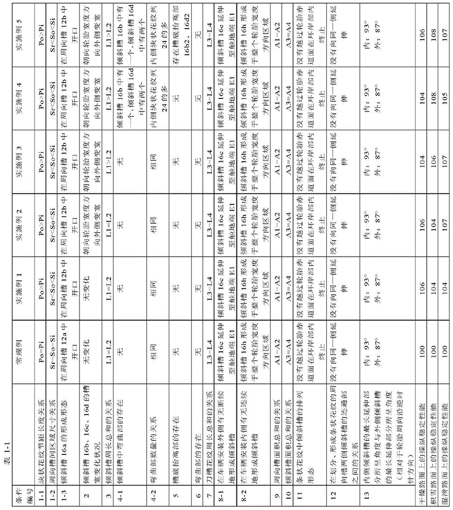
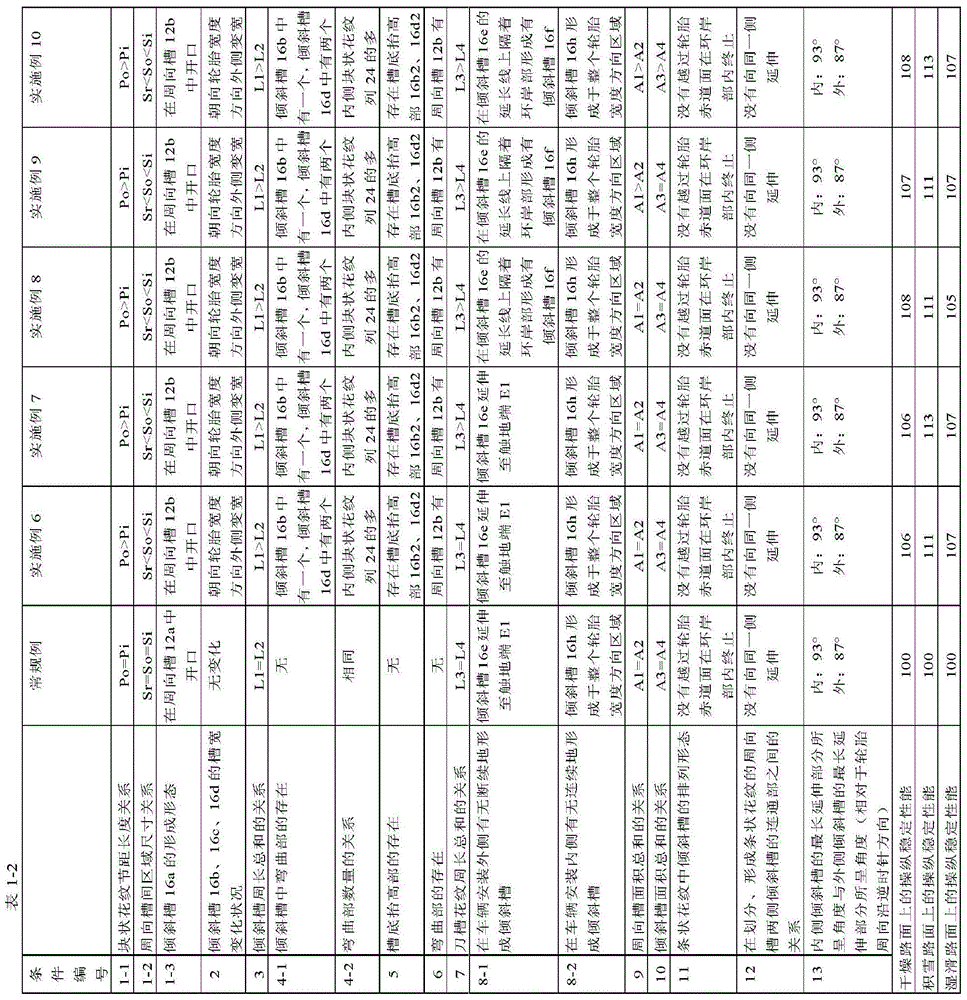
[0136] Set the tire size to 215 / 45R17 87W for figure 1 The components 12 to 30 shown are in accordance with the following conditions shown in Table 1-1 to Table 1-3:

[0137] (1-1) The relationship between the block pattern pitch length Po of the outer block pattern row 22 and the block pattern pitch length Pi of the inner block pattern row 24 (block pattern pitch length relationship),

[0138] (1-2) The relationship between the circumferential groove area sizes Sr, So, and Si of the strip pattern 20, the outer block pattern row 22, and the inner block pattern row 24 (the relationship between the circumferential groove area size),

[0139] (1-3) Formation of the inclined groove 16a for dividing and forming the striped pattern 20 (formation of the inclined groove 16a),

[0140] (2) The change of the groove width when the inclined grooves 16b, 16c that divide and form the outer block pattern row 22 and the inclined grooves 16d that divide and form the inner block pattern row 24 extend o...


PUM


Abstract

The purpose of the present invention is to provide a pneumatic tire that exhibits excellent operating stability whether the road surface is a dry road surface, a snow covered road surface or a wet road surface. A block pitch length (Po) of an outside block column (22) is greater than a block pitch length (Pi) of an inside block column (24). The tire width direction size in a region sandwiched between two circumferential grooves becomes smaller in the order of ribs (20), the outside block column (22), and the inside block column (24). Inclined grooves (16a) partitioning and forming the ribs (20) are opened only on a circumferential groove (12b) on a vehicle mount inside region partitioning and forming the ribs (20).

Description

Technical field [0001] The present invention relates to a pneumatic tire with improved handling stability on various road surfaces. Background technique [0002] A technique for improving the steering stability performance on various road surfaces has been disclosed (for example, refer to Patent Document 1). The technology disclosed in Patent Document 1 is to divide and form predetermined block patterns and strip patterns on each side of the vehicle installation, and adjust the groove area ratio to improve handling stability on dry roads and handling on snowy roads Stable performance. [0003] Prior art literature [0004] Patent literature [0005] Lee Document 1: Japanese Patent No. 4929466 [0006] Summary of the invention [0007] The problem to be solved by the invention [0008] In recent years, it is required to have excellent handling stability not only on dry roads and snowy roads, but also on wet roads. It is unclear whether it is possible to achieve excellent steering stabi...

Claims


Application Information

Patent Timeline
Patent Type & Authority Applications(China)
IPC IPC(8): B60C11/11B60C5/00B60C11/01B60C11/03B60C11/04B60C11/12B60C11/13
CPCB60C11/0306B60C11/0304B60C2011/1209B60C2011/0388B60C11/0318B60C2011/0381B60C2011/0346B60C11/1384B60C11/1392B60C2011/0395B60C2011/1295B60C11/0302B60C11/0309B60C11/0332B60C11/1236B60C11/1353B60C2011/0372B60C2011/1361
Inventor 村田尚久
Owner YOKOHAMA RUBBER CO LTD
Why Eureka
Try Eureka