
Robot cleaner and controlling method thereof

A control method and technology of cleaners, applied in the direction of cleaning action control, cleaning machinery, cleaning equipment, etc.

Inactive Publication Date: 2015-08-12
LG ELECTRONICS INC
View PDF9 Cites 73 Cited by
  • Summary
  • Abstract
  • Description
  • Claims
  • Application Information

AI Technical Summary

Problems solved by technology

Therefore, it does not make sense to use threshold detection sensors to differentiate rooms in clean areas without thresholds

Method used


Image

  • Robot cleaner and controlling method thereof
  • Robot cleaner and controlling method thereof
  • Robot cleaner and controlling method thereof

Examples


Embodiment Construction

[0084] In the following detailed description, reference is made to the accompanying drawings, which form a part hereof, and which illustrate by way of example specific embodiments of the invention. It is to be understood by those of ordinary skill in this technological field that other embodiments may be utilized, and structural, electrical, as well as procedural changes may be made without departing from the scope of the present invention. Wherever possible, the same reference numbers are used throughout the drawings to refer to the same or like parts.

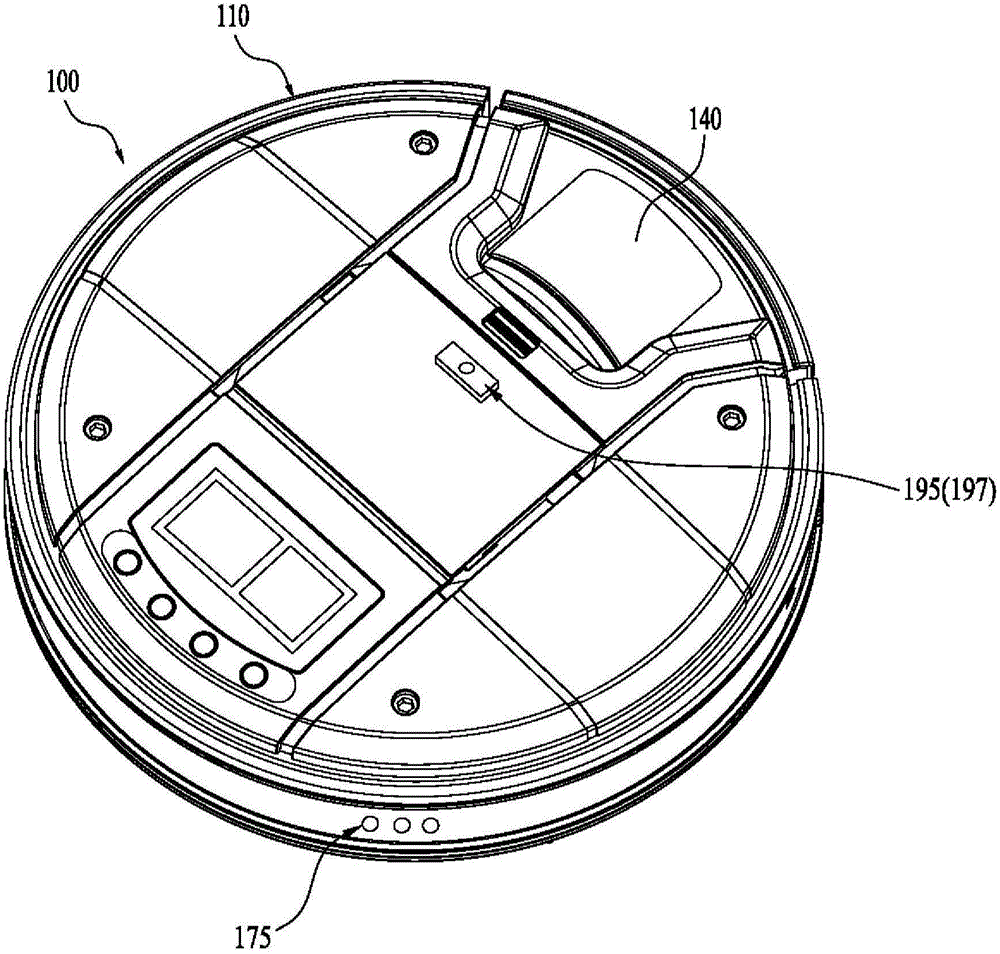
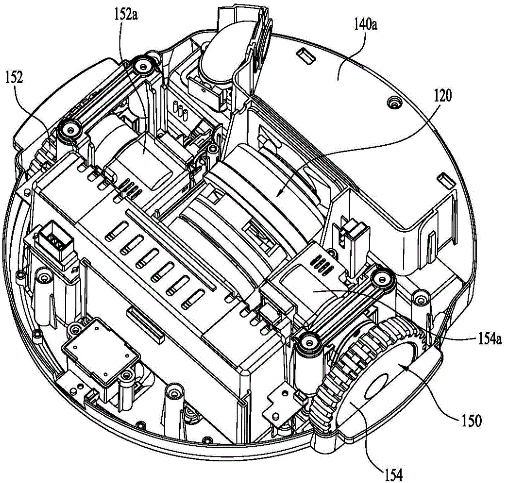
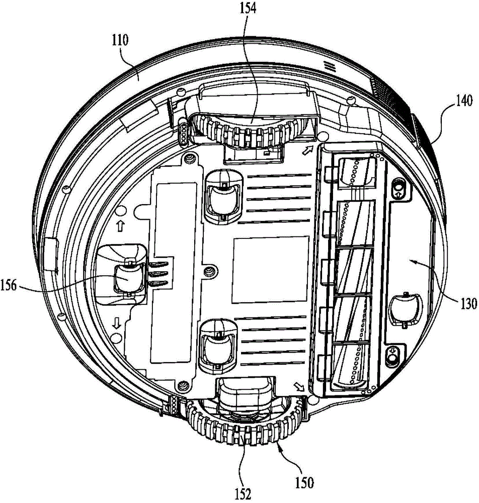
[0085] Refer to the following Figure 1 to Figure 4 The configuration of a robot cleaner according to one embodiment of the present invention will be described in detail.

[0086] figure 1 is a perspective view of a robot cleaner according to the prior art or an embodiment of the present invention. figure 2 is a perspective view of the internal structure of a robot cleaner according to an embodiment of the present inventi...


PUM


Abstract

A robot cleaner and controlling method thereof are disclosed. Accordingly, a cleaning area is partitioned with reference to a door by recognizing the door and the partitioned cleaning areas can be cleaned in consecutive order. The present invention includes the steps of deriving a door location in a cleaning area through an image information, composing a cleaning map by detecting an obstacle in the cleaning area, creating a room information for distinguishing a plurality of rooms partitioned with reference to the door from each other by having the derived door location reflected in the cleaning map, and performing a cleaning by room units distinguished from each other through the room information.

Description

[0001] Cross References to Related Applications [0002] This application claims the benefit of Korean Patent Application No. 10-2014-0016235 filed on February 12, 2014, which application is hereby incorporated by reference as fully set forth herein. technical field [0003] The present invention relates to a robot cleaner, and more particularly to a robot cleaner and a control method thereof. Although the present invention is suitable for a wide range of applications, it is particularly suitable for dividing the cleaning area with reference to the door by identifying the door, and then sequentially cleaning the divided cleaning areas. Background technique [0004] In general, a vacuum cleaner is a device for cleaning floors, carpets, etc. in a room. Specifically, the vacuum cleaner sucks air containing particles from the outside through an air suction device, and the air suction device installed in the cleaner body is configured with a motor, a fan, etc. to generate air su...

Claims


Application Information

Patent Timeline
Patent Type & Authority Applications(China)
IPC IPC(8): A47L11/24A47L11/40G05D1/02
CPCA47L2201/04A47L2201/06A47L11/4011G05D1/0274G05D1/0246A47L9/2857A47L9/28B25J13/08B25J9/16
Inventor 韩京民权泰范李东勋
Owner LG ELECTRONICS INC
Learn More