
dishwasher drying system

A drying system, dishwasher technology, applied in the direction of tableware washing machine/rinsing and washing machine parts, etc., can solve the problems affecting the dishwasher, electrical safety and reliability, etc., achieve low cost of improvement, and avoid the impact of water flow function , Improve the effect of drying efficiency

Active Publication Date: 2017-11-10
WUHU MIDEA SMART KITCHEN APPLIANCE MFG CO LTD
View PDF9 Cites 0 Cited by
  • Summary
  • Abstract
  • Description
  • Claims
  • Application Information

AI Technical Summary

Problems solved by technology

[0004] The object of the present invention is to overcome the shortcomings of the above-mentioned prior art and provide a drying system for dishwashers, which solves the problem that the condensed water produced in the drying process of existing dishwashers affects the electrical safety and reliability of dishwashers and the service life of wooden cabinets technical issues

Method used


Image

  • dishwasher drying system
  • dishwasher drying system
  • dishwasher drying system

Examples


Embodiment 1

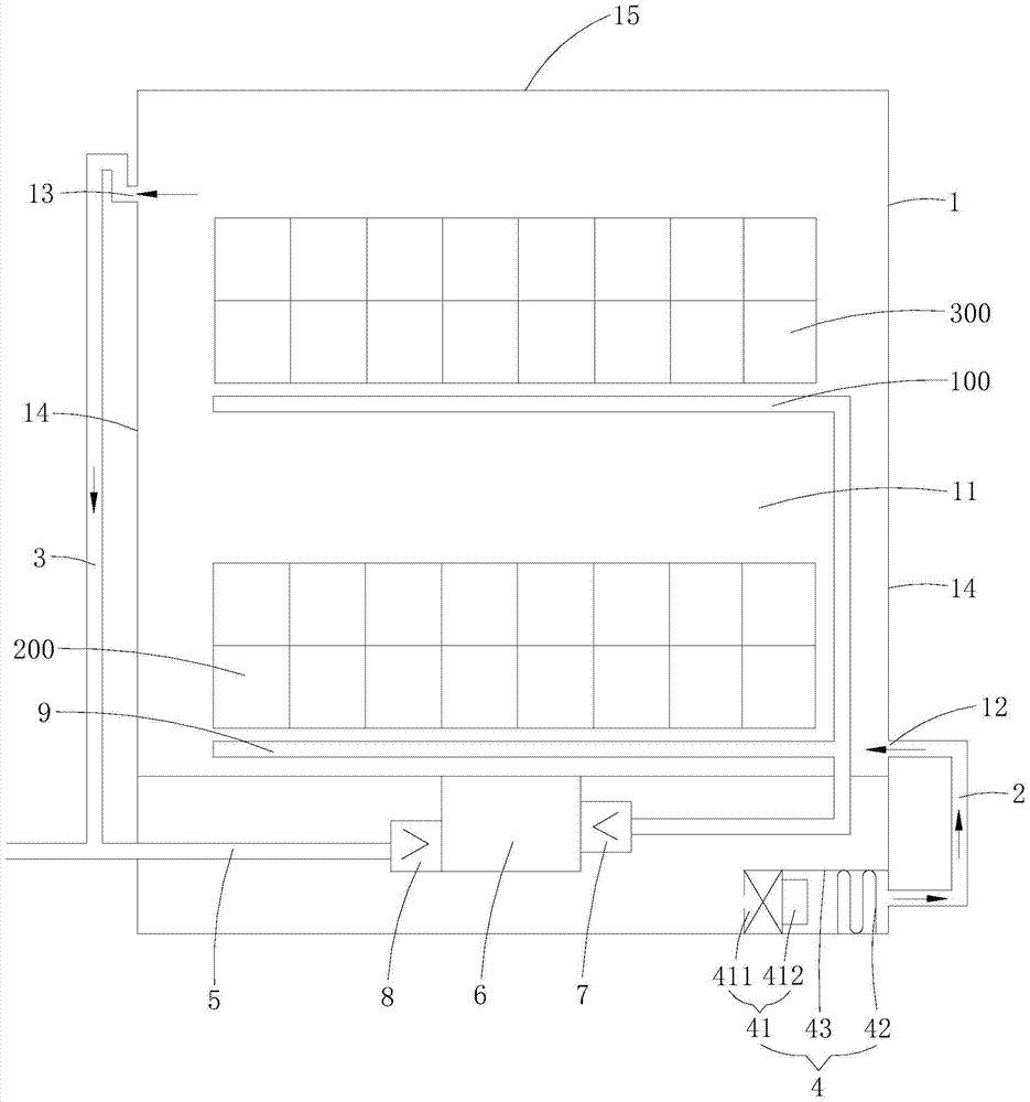
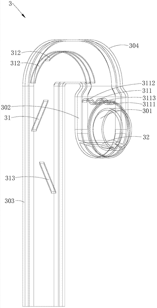
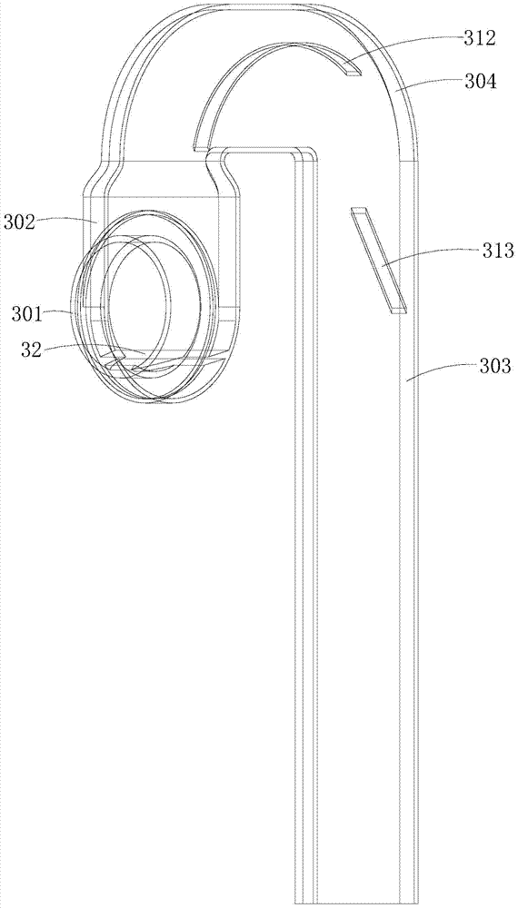
[0028] Such as Figure 1~4 As shown, the dishwasher drying system provided by Embodiment 1 of the present invention includes an inner container 1, an air inlet pipe 2, an air outlet pipe 3, a blowing device 4 and a drain pipe 5. The inner container 1 has an inner cavity 11, and an inner cavity The air inlet 12 communicated with 11 and the air outlet 13 communicated with the inner cavity 11, the air inlet 12 is connected to the blowing device 4 through the air inlet pipe 2, and the air outlet 13 is connected to the drain pipe 5 through the air outlet pipe 3. The dishwasher drying system provided in this embodiment connects the air inlet 12 and the blowing device 4 through the air inlet pipe 2, so that the blowing device 4 can blow air into the inner tank 1, thereby speeding up the discharge of hot and humid air from the inner tank 1 , Improve the drying efficiency of tableware. At the same time, it connects the air outlet 13 and the drain pipe 5 through the air outlet pipe 3, ...

Embodiment 2

[0045] Such as Figure 5 As shown, the dishwasher drying system provided in this embodiment differs from the first embodiment mainly in that the positions of the air inlet 12 , the air outlet 13 , and the blowing device 4 are different. Specifically, in this embodiment, the air inlet 12 is arranged near the top of the inner container 1, the blowing device 4 is installed above the inner container 1, the air outlet 13 is arranged near the bottom of the inner container 1, and the air inlet 12 and the air outlet 13 are respectively It runs through two opposite side panels 14 of the inner container 1 . The working principle of the dishwasher drying system provided in this embodiment is: the blowing device 4 continuously blows dry hot air into the inner container 1, and the dry hot air generated by the blowing device 4 enters the inner container 1 from the top of the inner cavity 11 The hot and dry air entering the inner cavity 11 will fully contact and mix with the hot and humid a...


PUM


Abstract

The invention is applicable to the field of dishwashers, and discloses a drying system for dishwashers, which includes an inner container, an air inlet pipe, an air outlet pipe, a blowing device and a drain pipe. The inner container has an inner cavity, an air inlet connected to the inner cavity, and The air outlet communicated with the inner cavity, the air inlet is connected to the blowing device through the air inlet pipe, and the air outlet is connected to the drain pipe through the air outlet pipe. In the present invention, the air outlet and the drain pipe are connected through the air outlet pipe, so that the hot and humid gas in the inner tank can be discharged into the air outlet pipe, and the condensed water generated by the condensation of the hot and humid gas in the air outlet pipe is achieved through the drainage of the air outlet pipe. It can flow to the drain pipe or flow back into the inner tank, which realizes the effective treatment of the hot and humid gas after it is discharged from the inner tank during the drying process, and eliminates the harm to electrical components and wooden cabinets caused by the condensed water formed after the hot and humid gas is discharged from the inner tank. , improve the electrical safety and reliability during the use of the dishwasher and ensure the service life of the wooden cabinet.

Description

technical field [0001] The invention belongs to the field of dishwashers, in particular to a drying system for dishwashers. Background technique [0002] A dishwasher is a household appliance for automatically washing tableware, which has been widely used in people's lives. Existing dishwashers are generally equipped with a drying system that can accelerate the drying speed of tableware, and the existing dishwasher systems generally realize rapid drying of tableware by discharging hot and humid gas from the inner tank. [0003] Although the existing dishwasher drying systems can play a certain role in improving the drying efficiency of tableware, there are still deficiencies in the specific applications of the existing dishwasher drying systems, which are specifically reflected in: the existing washing machine In the design of the bowl machine drying system, generally only consider how to improve the drying efficiency of the tableware by quickly discharging the hot and humi...

Claims


Application Information

Patent Timeline
Patent Type & Authority Patents(China)
IPC IPC(8): A47L15/48
Inventor 黄江远郭传江伊尔玛兹·多根高峰
Owner WUHU MIDEA SMART KITCHEN APPLIANCE MFG CO LTD
Learn More