
Magnetic suspension bearing lead structure and forming method thereof, magnetic suspension bearing and motor

A technology of magnetic suspension bearings and forming methods, applied in the direction of bearings, shafts, bearings, circuits, etc., can solve problems such as complex operation process, scratches on the surface insulation layer, poor insulation, etc.

Pending Publication Date: 2020-04-07
GREE ELECTRIC APPLIANCES INC
View PDF0 Cites 0 Cited by
  • Summary
  • Abstract
  • Description
  • Claims
  • Application Information

AI Technical Summary

Problems solved by technology

[0004] Because the magnetic suspension bearing has a winding coil, after winding the wire, it is necessary to lead out the enameled wire end. Since the enameled wire itself has a thin insulating layer, generally the enameled wire will not be led out directly, and a wire with an insulating layer will be connected to the end of the enameled wire as the lead out. The interface is welded with solder, and then the insulation protection is done on the surface. The operation process of this wiring method is complicated, and there is a risk of poor insulation after the surface insulation layer is scratched or broken.

Method used


Image

  • Magnetic suspension bearing lead structure and forming method thereof, magnetic suspension bearing and motor
  • Magnetic suspension bearing lead structure and forming method thereof, magnetic suspension bearing and motor
  • Magnetic suspension bearing lead structure and forming method thereof, magnetic suspension bearing and motor

Examples


Embodiment Construction

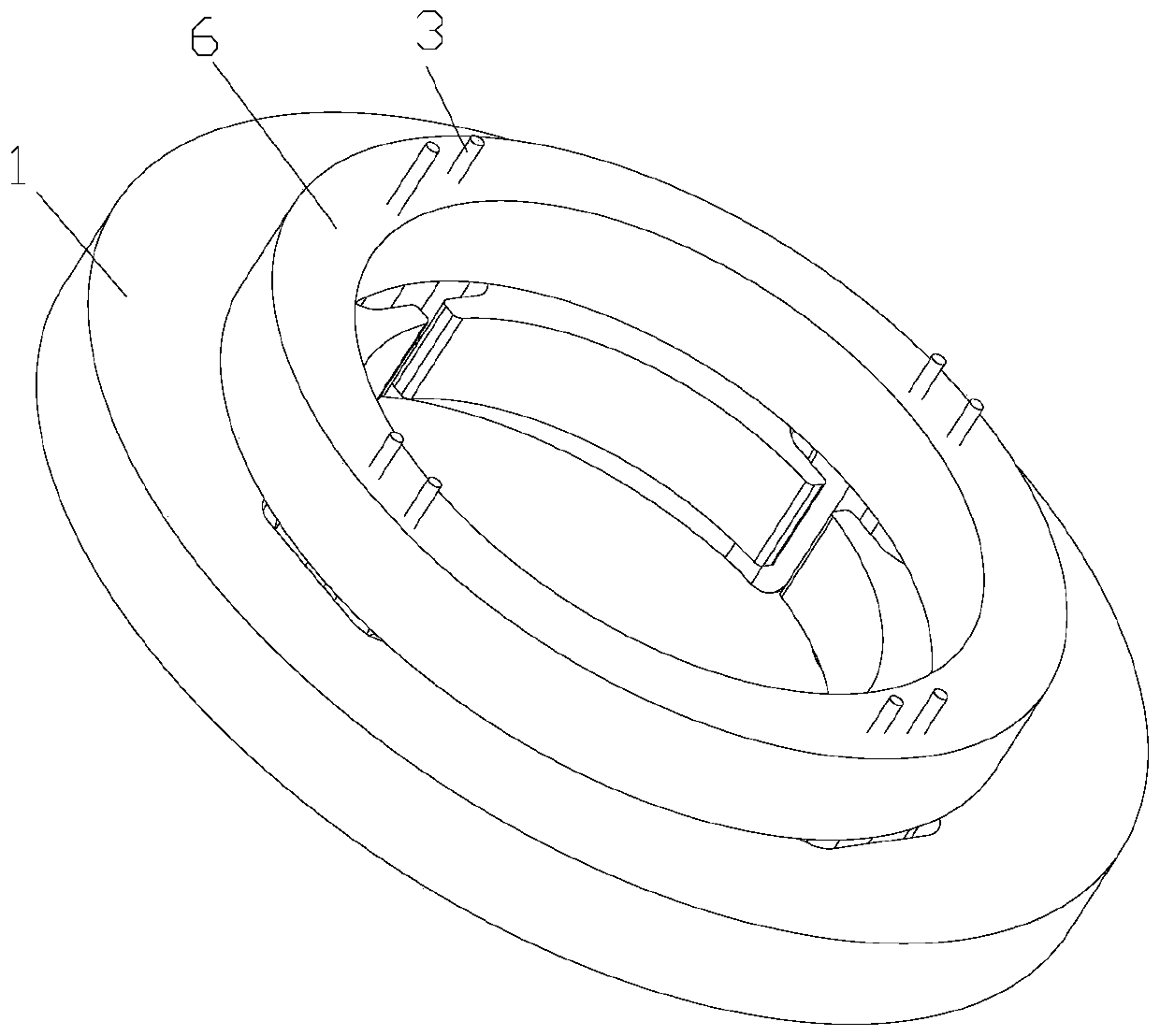
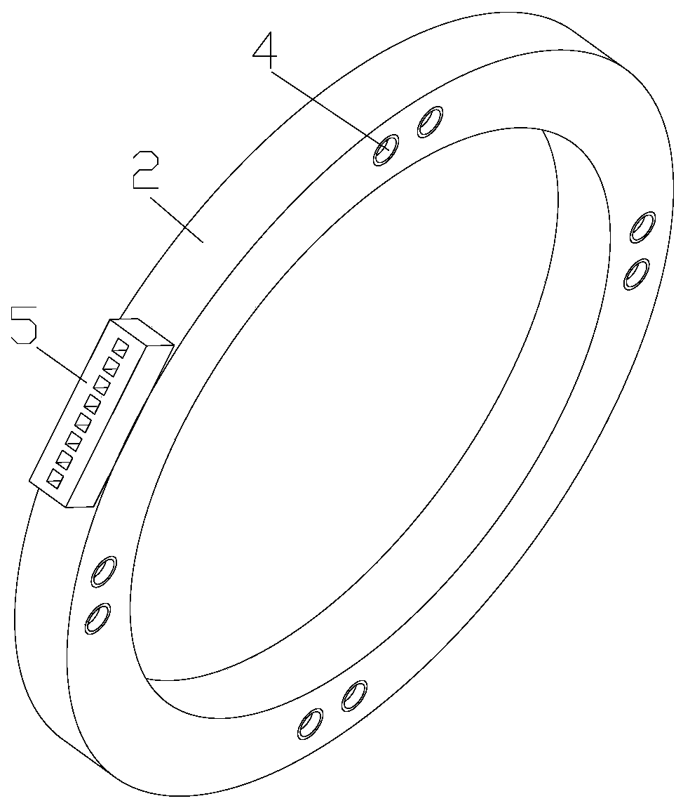
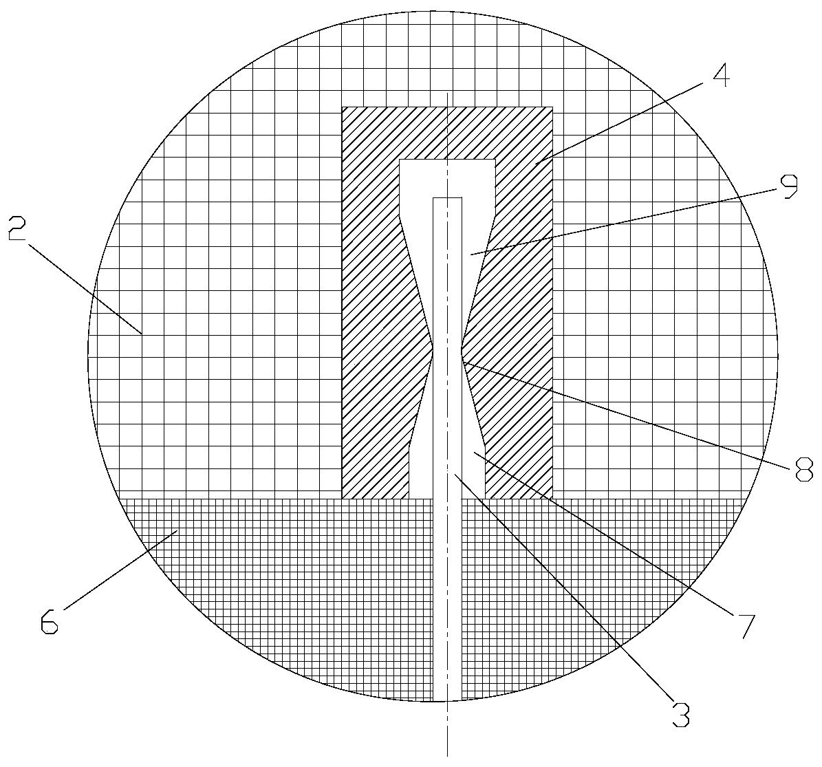
[0034] see in conjunction Figure 1 to Figure 3 As shown, according to the embodiment of the present application, the lead wire structure of the magnetic suspension bearing includes a terminal board 2, a stator core 1 and a stator winding arranged on the stator core 1. The stator winding includes a plurality of coil joints, and each coil joint is correspondingly provided with A connecting post 3, the connecting board 2 includes a connecting plug 4 and an outlet connector 5, the connecting plug 4 and the connecting post 3 are plugged in one-to-one correspondence, and the connecting terminals of the connecting plug 4 and the outlet connector 5 are connected by wires in one-to-one correspondence.

[0035] The lead wire structure of the magnetic levitation bearing has modified the coil joints so that the coil joints are in the form of terminal posts, and then the connection between the coil structure and the terminal plug 4 is realized by means of plugging, so that the terminal pos...


PUM


Abstract

The invention provides a magnetic suspension bearing lead structure and a forming method thereof, a magnetic suspension bearing and a motor. The magnetic suspension bearing lead structure comprises awiring board (2), a stator iron core (1) and a stator winding arranged on the stator iron core (1), wherein the stator winding comprises a plurality of coil joints, each coil joint is correspondinglyprovided with a binding post (3), the wiring board (2) comprises wiring plugs (4) and outgoing line joints (5), the wiring plugs (4) and the binding posts (3) are in one-to-one correspondence plug-inconnection, and wiring terminals of the wiring plugs (4) and the outgoing line joints (5) are in one-to-one correspondence connection through wires. According to the magnetic suspension bearing lead structure, the wiring mode of the magnetic suspension bearing can be simplified, and the electrical safety of the wiring connection part of the magnetic suspension bearing is improved.

Description

technical field [0001] The application relates to the technical field of electric motors, in particular to a magnetic suspension bearing lead wire structure and a forming method thereof, a magnetic suspension bearing and a motor. Background technique [0002] Magnetic suspension bearings have a series of excellent qualities such as no contact, no wear, high speed, high precision, no need for lubrication and sealing, and are a high-tech product integrating electromagnetics, electronic technology, control engineering, signal processing, and mechanics. [0003] Magnetic suspension bearings are divided into three types: active, passive, and hybrid. Active magnetic suspension bearings have high rigidity and can be precisely controlled, but require a large volume and power consumption to generate unit bearing capacity; passive magnetic suspension bearings use the attraction between magnetic materials Or repulsion realizes the suspension of the rotor, and the stiffness and damping ...

Claims


Application Information

Patent Timeline
IPC IPC(8): F16C32/04H01F27/28
CPCF16C32/0459F16C32/0461F16C32/0468H01F27/2828
Inventor 谭建明胡余生陈彬张小波张芳龚高张超王飞
Owner GREE ELECTRIC APPLIANCES INC
Learn More