Self-adaptive binding design for exoskeleton robot shank

An exoskeleton robot, self-adaptive technology, applied in the direction of equipment to help people walk, physical therapy, etc., can solve the problems of easy damage, affecting the comfort of binding, secondary injury of the wearer's limbs, etc., to improve comfort, The effect of reducing quality and manufacturing difficulty

Active Publication Date: 2015-08-12
布法罗机器人科技(成都)有限公司 +1
7 Cites 16 Cited by

AI-Extracted Technical Summary

Problems solved by technology

However, since the knee joints of skeletal robots at home and abroad are basically simple hinge structures, which completely ignore the complex movements of the human knee joints, there will often be slight dislocation of the joints during the flexion and extension of the calf.
This misalignment will cause the position deviation between the calf stem of the exoskeleton and the human calf,...

Method used

The working process of the present invention is as follows: when the wearer uses it, the human knee joint is aligned with the spline output shaft 33 output by the knee joint turbine in Fig. 1, the shank is placed in the carbon fiber supporting plate 58 in Fig. When the knee joint is bound with a strap, when the knee joint flexes and extends, since the human knee joint is a complex variable-axis movement, while the exoskeleton knee joint is a single-axis movement, this mismatch will inevit...

Abstract

The invention discloses a self-adaptive binding design for an exoskeleton robot shank. The self-adaptive binding design comprises a motor (1), a speed reducer (2), a worm gear and worm (3), a shank connecting rod (4) and a shank binding device (5), wherein the shank binding device (5) comprises a shank rod (51), a sleeve (52), a pin (53), a binding sliding piece (54), a rotary pin (55), a pin fixing piece (56), a binding supporting strip (57) and a carbon fiber supporting plate (58); the shank rod (51) is connected with the shank connecting rod (4). The self-adaptive binding design disclosed by the invention has the beneficial effects that the problems of deviation generated by microcosmic malposition of a man-machine system along the radial direction of a shank and tangential rotating deviation generated by the microcosmic malposition of the man-machine system are solved, any active execution mechanisms do not need to be added any more through the self-adaptive binding design, the mass and the complexity of the system are not increased by a large amount, and the wearing comfort of a recovery exoskeleton is greatly increased.

Application Domain

Technology Topic

Image

  • Self-adaptive binding design for exoskeleton robot shank
  • Self-adaptive binding design for exoskeleton robot shank

Examples

  • Experimental program(1)

Example Embodiment

[0013] The present invention will be further described below in conjunction with the accompanying drawings. The protection scope of the present invention is not limited to the following:
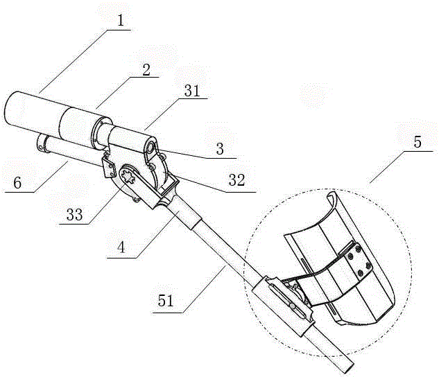
[0014] Such as figure 1 As shown, an exoskeleton robot self-adaptive binding design for the calf includes a motor 1, a reducer 2, a worm gear 3, a calf connecting rod 4, and a calf binding device 5. The motor 1 and the reducer 2 are screwed Connected to form a knee joint driver. In this embodiment, the motor 1 is a brushless straight-cylinder motor, the reducer 2 is a planetary reducer, and the upper end of the worm and worm 3 is provided with an upper fixed shell 31, and the worm and worm 3 side A side fixed shell 32 is provided in the worm and worm 3, a spline output shaft 33 is installed in the worm and worm 3, a thigh connecting rod 6 is installed at the front end of the worm and worm 3, and the lower leg connecting rod 4 is mounted on two spline output shafts 33. The output shaft of the reducer 2 is located in the upper fixed shell 31 and is connected with the worm of the worm gear 3. Its power is transmitted by the worm gear of the worm gear 3, and then output through the spline output shaft 33, so that the power is transmitted to On the calf rod 51; such as figure 2 As shown, the calf binding device 5 includes a calf rod 51, a sleeve 52, a pin 53, a binding slider 54, a rotating pin 55, a pin fixing member 56, a binding tow 57, and a carbon fiber support plate 58, so The calf rod 51 is connected to the calf connecting rod 4. In this embodiment, the calf rod 51 is made of carbon alloy material to ensure the strength of the exoskeleton structure. The calf rod 51 is provided with a through hole 59 and one end of the pin 53 It is fixedly arranged in the through hole 59, the other end of the pin 53 is located in the sliding groove of the binding slider 54 to play a sliding limit function. The sleeve 52 is sleeved in the binding slider 54 and forms the calf diameter In this embodiment, the sleeve 52 is a polytetrafluoroethylene sleeve, which can reduce the sliding resistance. One end of the rotating pin 55 is connected to the binding sliding member 54 through a thread, and the other end is built into the pin fixing member. On the inner side of 56, the binding tow 57 and the carbon fiber support plate 58 are connected by screws to form a calf support assembly, and the binding tow 57 and the pin fixing member 56 are connected by screws.
[0015] The working process of the present invention is as follows: when the wearer uses, connect the human knee joint with figure 1 The spline output shaft 33 of the middle knee joint turbine output is aligned, and the lower leg is placed on figure 2 The middle carbon fiber support plate 58 is bound by a flexible strap. When the knee joint performs flexion and extension exercises, because the human knee joint is a complex variable-axis motion, and the exoskeleton knee joint is a single-axis motion, this is not Correspondence will inevitably lead to a slight misalignment of the joints, resulting in a pulling force along the radial direction of the lower leg and a torsion force generated by the tangential rotation deviation at the lower leg binding. The calf tie of the present invention passes figure 2 The middle binding slider 54 releases the radial restraint of the calf and the rotation pin 55 releases the tangential rotation restraint to adapt to the deviation of the human-machine movement process, thereby eliminating the drag and torsion force generated by the exoskeleton binding on the human body, thereby improving the rehabilitation The wearing comfort of the bones.

PUM

no PUM

Description & Claims & Application Information

We can also present the details of the Description, Claims and Application information to help users get a comprehensive understanding of the technical details of the patent, such as background art, summary of invention, brief description of drawings, description of embodiments, and other original content. On the other hand, users can also determine the specific scope of protection of the technology through the list of claims; as well as understand the changes in the life cycle of the technology with the presentation of the patent timeline. Login to view more.

Similar technology patents

Control method of air conditioner and air conditioner

Owner:GD MIDEA AIR-CONDITIONING EQUIP CO LTD +1

Classification and recommendation of technical efficacy words

  • Improve comfort

Treatment of teeth by aligners

InactiveUS20060275731A1Improve comfortReduce treatment time and costImpression capsAdditive manufacturing apparatusDental treatmentsOrthodontics
Owner:ALIGN TECH

Fan

Owner:UNIVERSAL SAFETY RESPONSE +1

Cleaning method and device for indoor heat exchanger of air conditioner

ActiveCN104848738AAchieve high temperature sterilization functionImprove comfortCleaning heat-transfer devicesSpace heating and ventilation safety systemsFrostEngineering
Owner:GREE ELECTRIC APPLIANCES INC
Why Eureka
Try Eureka