
Side bending mold for back plate

A mold and backplane technology, applied in the field of backplane side-folding molds, can solve the problems of surface abrasion or scratches, complex structure, easy sliding of workpieces, etc.

Inactive Publication Date: 2015-08-12
昆山电子羽电业制品有限公司
View PDF6 Cites 2 Cited by
  • Summary
  • Abstract
  • Description
  • Claims
  • Application Information

AI Technical Summary

Problems solved by technology

In the prior art, the structure of the bending mold is complicated, and the operation is inconvenient, and during the bending process, the workpiece is easy to slide, causing surface wear or scratches, which affects the appearance quality of the bent parts

Method used


Image

  • Side bending mold for back plate

Examples


Embodiment Construction

[0014] Combine below figure 1 And further illustrate the technical solution of the present invention through specific examples.

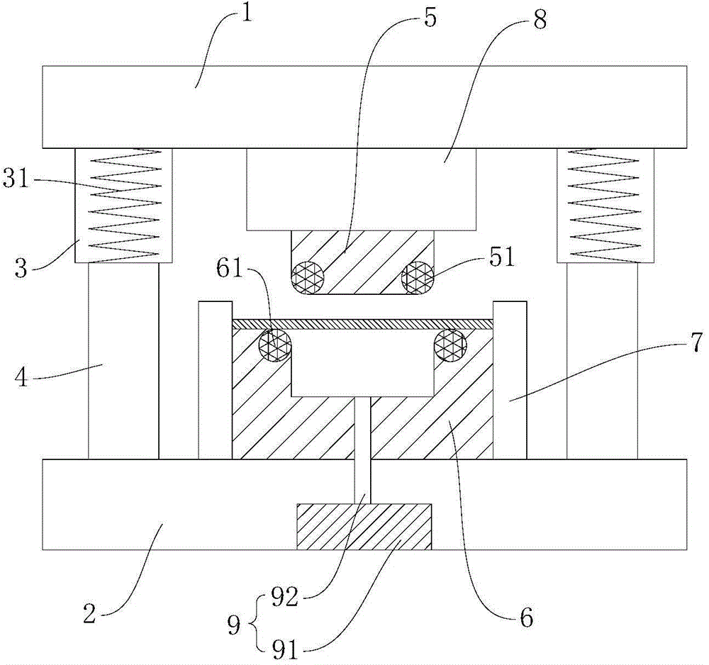
[0015] A side folding mold for a back panel, comprising an upper template 1 and a lower template 2, the upper template 1 and the lower template 2 are arranged oppositely, the lower surface of the upper template 1 is provided with a guide sleeve 3, and the upper surface of the lower template 2 is provided with a guide column 4. The guide column 4 can move up and down in the guide sleeve 3, so that the upper template 1 moves up and down relative to the lower template 2. A return spring 31 is arranged in the guide sleeve 3, and the upper part of the return spring 31 is connected with the upper template 1 to reset The bottom of the spring 31 is connected with the guide column 4, the upper template 1 is connected with the punch 5, the two ends of the lower end surface of the punch 5 are provided with the first roller 51, the lower template 2 is connected...


PUM


Abstract

The invention discloses a side bending mold for a back plate. The side bending mold for the back plate comprises an upper mold plate and a lower mold plate, wherein the upper mold plate is provided with a guide sleeve; the lower mold plate is provided with a guide column; the guide column can move up and down in the guide sleeve; a return spring is arranged in the guide sleeve; the upper mold plate is connected with a male mold; a first roller is arranged at each of the two ends of the lower end surface of the male mold; the lower mold plate is connected with a female mold; a second roller is arranged at each of the two ends of the upper end surface of the female mold; stop blocks used for positioning a workpiece are arranged at the parts, positioned on the two sides of the female mold, of the lower mold plate. During mold closing, the upper mold plate moves down relative to the lower mold plate, the workpiece between the two stop blocks is bent downwards, and after the workpiece is bent, the upper mold plate moves up and returns under the action of the return spring. The side bending mold for the back plate is simple in structure and convenient to operate, the surface abrasion caused by sliding of the workpiece at the corner is avoided, and the bending quality of the workpiece is guaranteed. The side bending mold for the back plate is simple in structure and convenient to operate; moreover, the surface abrasion caused by bending of the workpiece can be avoided, and the bending quality of the workpiece is improved.

Description

technical field [0001] The invention relates to the technical field of molds, in particular to a side folding mold for a back panel. Background technique [0002] With the progress of society and the development of economy, the application of mechanical products is becoming more and more extensive in daily life. Among them, bending parts account for a large proportion of mechanical products. In the prior art, the structure of the bending die is complicated, and the operation is inconvenient, and during the bending process, the workpiece is easy to slide, causing surface wear or scratches, which affects the appearance quality of the bent part. Contents of the invention [0003] The object of the present invention is to provide a side-folding mold for back panels, which has a simple structure and is easy to operate, and can avoid surface abrasion of workpieces during bending, thereby improving the bending quality of workpieces. [0004] For reaching this purpose, the presen...

Claims


Application Information

Patent Timeline
IPC IPC(8): B21D37/10B21D37/12B21D45/02
CPCB21D37/10B21D37/12B21D45/02
Inventor 李国新
Owner 昆山电子羽电业制品有限公司
Learn More