Compressive overload protection device

A technology of overload protection and compression spring, which is applied in the direction of maintenance and safety accessories, metal processing machinery parts, metal processing equipment, etc., can solve problems such as breaking, increased axial force of taps, poor stability, etc., and achieve the effect of preventing breakage

Inactive Publication Date: 2015-08-12
SHENZHEN BITLE MACHINERY CO LTD
View PDF9 Cites 4 Cited by
  • Summary
  • Abstract
  • Description
  • Claims
  • Application Information

AI Technical Summary

Problems solved by technology

This patented technology only plays the role of radial overload protection in actual use. Since the tap needs to move downward and rotate at the same time when it is working, the tap is simultaneously subjected to circumferential torque and axial pressure, and the torque is much greater than the pressure. In this patented technology, the connection between the steel ball 3 and the circular arc groove on the outer wall of the tap chuck 1 is used for overload protection. Since the radial and axial contact between the steel ball 3 and the circular arc groove is consistent, its radial The preloading force and the axial preloading force are equal, because the radial torque that the tap bears is much greater than the axial pressure it bears, so the movement of the tap is invalid due to excessive radial force, but the machining center will continue to feed in the axial direction , causing the axial force of the tap to gradually increase and lead to breakage. In addition, this patented technology uses a spring to provide preloading force. The spring is an elastic structure. Repeated compression is easy to cause damage, short service life and poor stability.

Method used


Image

  • Compressive overload protection device
  • Compressive overload protection device

Examples


Embodiment Construction

[0022] The present invention will be further described below in conjunction with the drawings:

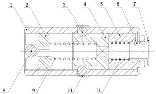
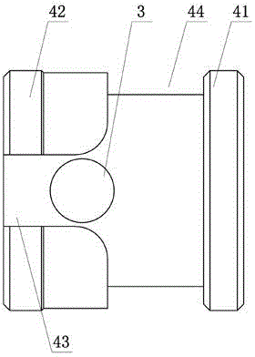
[0023] Such as Figure 1 to Figure 2 As shown, the technical solution adopted by the present invention is as follows: a compression overload protection device, including a clamp sleeve 1, an adjusting nut 2, a steel ball 3, a force transmission sleeve 4, a reducing sleeve 5, a compression spring 9 and a centering component, wherein , The above-mentioned clamp sleeve 1 is a cylindrical structure, the inner wall of the left end of the clamp sleeve 1 is provided with internal threads, and the adjusting nut 2 is threadedly connected with the inner wall of the clamp sleeve 1; the right side of the adjusting nut 2 is provided with a force transmission sleeve 4 and a compression spring 9. It is arranged between the adjusting nut 2 and the force transmitting sleeve 4. The two ends of the adjusting nut 2 respectively bear the end faces of the adjusting nut 2 and the force transmitting slee...


PUM


Abstract

The invention discloses a compressive overload protection device. The compressive overload protection device comprises a clamp sleeve, an adjusting nut, steel balls, a force transfer sleeve, a reduction sleeve, a compression spring and a centering assembly. The clamp sleeve is of a cylindrical structure, an internal thread is arranged on the inner wall of the left end of the clamp sleeve, and the adjusting nut is connected with the inner wall of the clamp sleeve through threads. The force transfer sleeve is arranged on the right side of the adjusting nut, the compression spring is arranged between the adjusting nut and the force transfer sleeve, and the two ends of the adjusting nut abut against the end face of the adjusting nut and the end face of the force transfer sleeve respectively. The steel balls are embedded in guide grooves of the force transfer sleeve so that the force transfer sleeve can be limited in the radial direction, and the upper portions of the steel balls are clamped into through holes formed in a wall body of the clamp sleeve so that the steel balls can be limited and fixed. The reduction sleeve is tightly attached to the force transfer sleeve to be arranged on the right side of the force transfer sleeve, the centering assembly is arranged in the reduction sleeve, and a screw tap is inserted in the force transfer sleeve in an inward mode through the centering assembly. By the adoption of the double-section structure, an elastic overload protection structure is combined with a rigid overload protection structure, and axial overload protection and radial overload protection are achieved at the same time.

Description

Technical field [0001] The invention relates to the field of tapping drill bits, in particular to a compression overload protection device. Background technique [0002] Drilling and tapping are commonly used in the machining process. Drilling refers to the operation of making holes in solid materials with a drill. Tapping is the use of a certain torque to screw the tap into the bottom hole to be drilled to produce internal threads. Drilling and tapping need to drive the drill bit and the tap to rotate at high speed, in order to convert the torque of the shaft into the driving force for downward drilling and tapping. The drill and the tap are respectively fixed on the chuck and driven by the chuck to rotate at high speed. High-speed rotating drills and taps need overload protection devices to prevent breakage due to excessive overload or twisting due to excessive torque. [0003] The Chinese invention patent with the authorized announcement number CN 2504024Y discloses a "tapping ...

Claims


Application Information

Patent Timeline
Patent Type & Authority Applications(China)
IPC IPC(8): B23Q11/04
CPCB23Q11/04
Inventor 曾建军
Owner SHENZHEN BITLE MACHINERY CO LTD
Why Eureka
Try Eureka