Laser marking method, laser marking machine and laser marking system

A laser marking method and technology of laser marking machine, applied in the field of laser marking method, laser marking machine and system, can solve the problems of inaccurate marking point, low marking resolution, small area, etc.

Active Publication Date: 2015-08-12
MAXPHOTONICS CORP
View PDF6 Cites 19 Cited by
  • Summary
  • Abstract
  • Description
  • Claims
  • Application Information

AI Technical Summary

Problems solved by technology

However, due to the small unit area, the naked eye cannot see his existence at all, and can only feel the continuous change of the picture
The existing marking technology adopts the method of separating marking control an

Method used


Image

  • Laser marking method, laser marking machine and laser marking system
  • Laser marking method, laser marking machine and laser marking system
  • Laser marking method, laser marking machine and laser marking system

Examples


Embodiment Construction

[0069] In order to make the above objects, features and advantages of the present application more obvious and comprehensible, the present application will be further described in detail below in conjunction with the accompanying drawings and specific implementation methods.

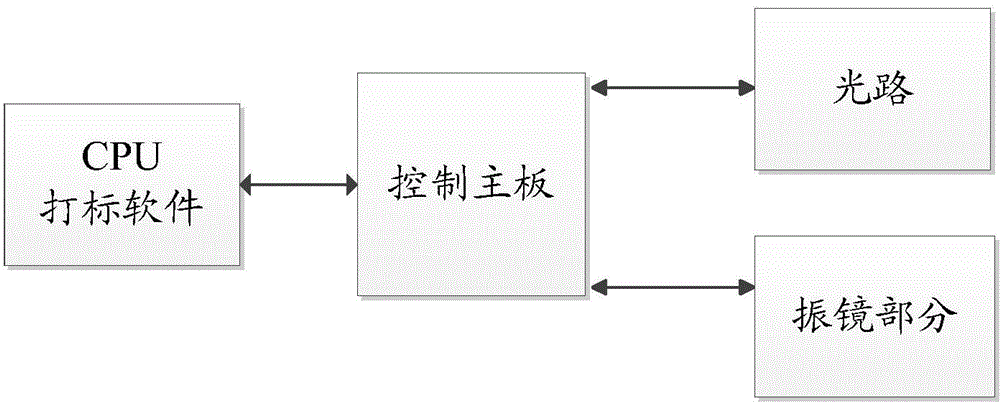
[0070] refer to figure 1 It is a structural block diagram of a general marking machine. A general marking machine includes: CPU / marking software, control board, optical path, and vibrating mirror. Among them, the CPU / marking software is mainly responsible for the processing and editing of graphics (bitmaps, vector graphics, text, two-dimensional codes, etc.), and will convert the graphics into graphics that can be recognized by the control board according to the operator's settings and marking conditions. Marking instruction, the marking instruction is the action splitting of the marking machine, and each instruction is an action of the marking machine. After the command is generated, the command is enc...


PUM


Abstract

The embodiment of the application provides a laser marking method. The method comprises following steps: a control mainboard receives coordinates and grey values of target image pixel points; the control mainboard calculates the output power of the target image pixel points according to the grey values; and the control mainbaord controls a laser to output laser light aiming at the target image pixel points with corresponding output power according to the displacement of a vibration mirror. According to the application, an independent pixel point can embody the change of the grey value by the adjustment of the output power of the target image pixel points (marking points), so that the grey value of the image can be presented. The coordinates of the pixel points of the grey-scale image is calculated according to preset resolutions, and the coordinates of the pixel points are not adjusted during a marking process, so that the resolution of the grey-scale image can be guaranteed. A manner that the gray scale is embodied through the density of the marking points is abandoned, and each marking point can embody the grey scale, so that the marking efficiency is relatively improved.

Description

technical field [0001] The present application relates to the technical field of laser marking, in particular to a laser marking method, a laser marking machine and a system. Background technique [0002] In the existing marking machine, the marking software will retain the set pixels according to the resolution setting of the operator, and perform gray calculation according to the three sub-pixels of red, green and blue to obtain the gray value of each pixel. The grayscale difference of the image can be presented by the number of marking points per unit area, that is, the grayscale presentation can be realized by the density of marking points. However, due to the small unit area, the naked eye cannot see his existence at all, and can only feel the continuous change of the picture. The existing marking technology adopts the method of separating marking control and laser control. The laser control adopts rough line segment control, which cannot be accurate to the control of ...

Claims


Application Information

Patent Timeline
IPC IPC(8): B41J2/435B41J3/407
Inventor 宋君何高锋蒋峰
Owner MAXPHOTONICS CORP
Why Eureka
Try Eureka