
engine oil cooler seat

A technology of engine oil and cooler, which is applied in the direction of engine components, machine/engine, engine lubrication, etc. It can solve the problems of poor cooling effect, harsh working temperature of lubricating oil, and inability to control the flow of cooling water, etc., and achieve a simple product structure , Energy utilization rate improvement, the effect of easy maintenance

Active Publication Date: 2017-05-10
WUXI KIPOR POWER CO LTD
View PDF5 Cites 0 Cited by
  • Summary
  • Abstract
  • Description
  • Claims
  • Application Information

AI Technical Summary

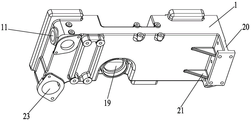
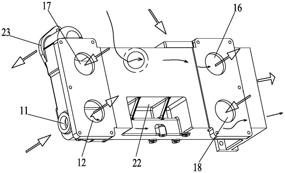
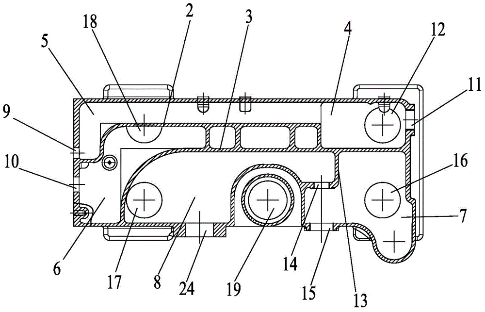
Problems solved by technology

[0002] The original oil cooler seat is only used to support the oil cooler and provide a path for the cooling water. However, with the improvement of people's demand for engine performance, the working temperature of the lubricating oil is becoming increasingly strict. The ordinary oil filter seat cannot The flow of cooling water is regulated, so that the working temperature of lubricating oil cannot be precisely controlled, and the cooling effect is poor

Method used


Image

  • engine oil cooler seat
  • engine oil cooler seat
  • engine oil cooler seat

Examples


Embodiment Construction

[0010] The present invention will be further described below in conjunction with specific drawings and embodiments.

[0011] Such as Figure 1~3 As shown, it includes a body 1, a first partition plate 2, a second partition plate 3, a first oil chamber 4, a second oil chamber 5, a third oil chamber 6, a first water chamber 7, and a second water chamber 8. , The first oil outlet 9, the second oil outlet 10, the first oil inlet 11, the second oil inlet 12, the third partition plate 13, the first through hole 14, the second through hole 15, the first Water inlet 16, first water outlet 17, third oil inlet 18, third water inlet 19, mounting seat 20, stiffener 21, groove 22, water pump connection port 23, second water hole 24, etc.

[0012] Such as Figure 1~3 As shown, an engine oil cooler seat of the present invention includes a body 1. One end of the body 1 along the length direction is provided with a first oil outlet 9 and a second oil outlet 10, and the other end is provided with a ...


PUM


Abstract

The invention belongs to the field of engine equipment, and relates to an engine oil cooler seat, which includes a body, and one end of the body along the length direction is provided with a first oil outlet and a second oil outlet, and the other end is provided with a first oil inlet. The inner cavity of the body is provided with a first partition plate and a second partition plate; the first partition plate and the second partition plate are connected by ribs arranged parallel to each other, and the first partition plate A third oil chamber is formed between the partition plate and the second partition plate, and a second oil chamber and a first oil chamber are formed between the first partition plate and the body; the first oil chamber communicates with the first The oil inlet, the second oil chamber communicates with the first oil outlet, and the third oil chamber communicates with the second oil outlet. The product of the invention has a simple and reasonable structure, and can accurately control the flow of cooling water in the working process, thereby improving the energy utilization rate; meanwhile, the product has a simple structure and is convenient for maintenance.

Description

Technical field [0001] The invention belongs to the field of engine equipment and relates to an engine oil cooler seat. Background technique [0002] The original oil cooler seat is only used to support the oil cooler and provide a path for cooling water. However, as people’s requirements for engine performance increase, the working temperature of lubricating oil is becoming increasingly strict, and ordinary oil filter seats cannot The flow rate of the cooling water is regulated, so that the working temperature of the lubricating oil cannot be accurately controlled, and the cooling effect is poor. Summary of the invention [0003] The purpose of the present invention is to overcome the deficiencies in the prior art and provide a simple, ingenious and reasonable engine oil cooler seat, which can accurately control the cooling water flow according to the engine operation requirements, thereby controlling the cooling Liquid temperature. [0004] According to the technical solution pr...

Claims


Application Information

Patent Timeline
Patent Type & Authority Patents(China)
IPC IPC(8): F01M5/00
CPCF01M5/002
Inventor 肖亨琳张正松张荣其高韬陈林
Owner WUXI KIPOR POWER CO LTD
Learn More