Turbine with Dynamic Compensation Device

A technology of power compensation and water turbine, which is applied in the direction of machine/engine, reaction engine, hydroelectric power generation, etc., can solve problems such as affecting the cooling effect of the system, and achieve the effects of high compensation efficiency, improved energy utilization rate and simple structure

Active Publication Date: 2017-01-18
南京峡谷能源科技有限公司
View PDF4 Cites 0 Cited by
  • Summary
  • Abstract
  • Description
  • Claims
  • Application Information

AI Technical Summary

Problems solved by technology

[0003] The purpose of the present invention is to design a water turbine with a power compensation device for the problem that the existing water turbine speed is affected by the insufficient pressure of the system and affects the cooling effect of the system.

Method used


Image

  • Turbine with Dynamic Compensation Device
  • Turbine with Dynamic Compensation Device

Examples


Embodiment Construction

[0022] The present invention will be further described below in conjunction with the accompanying drawings and embodiments.

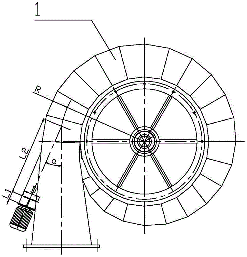
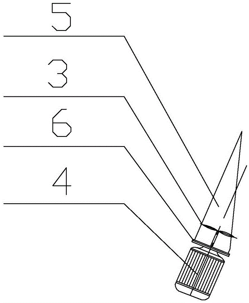
[0023] Such as Figure 1-2 shown.

[0024] A water turbine with a power compensation device, which includes a volute 1, the water inlet of the volute 1 communicates with the water outlet of the water inlet pipe 2, and an oblique installation such as figure 2 The shown pressurized flow channel 5, the water inlet and outlet of the pressurized flow channel 5 are connected to the side of the water inlet pipe 2, and a section that enables the compensation water from the water inlet pipe to enter the section is installed in the described pressurized flow channel 5. The cooling water entered by L1 is accelerated and pressurized, then enters the water inlet pipe 2 again and merges with the cooling water from the water inlet pipe 2 (confluence section length L2), and then enters the supercharging vane 3 in the volute, and the drive shaft of the supercharging v...


PUM


Abstract

A hydraulic turbine with a power compensation device comprises a volute (1). The water inlet of the volute (1) is communicated with the water outlet of a water inlet pipe (2). The hydraulic turbine is characterized in that a pressurization flow channel (5) is arranged obliquely at one side of the water inlet pipe (2) of the volute (1), the water inlet and the water outlet of the pressurization flow channel (5) are communicated with the side of the water inlet pipe (2), a pressurization blade (3) which can make cooling water entering the water inlet pipe be quickly pressurized, reenter the water inlet pipe (2), converge with cooling water in the water inlet pipe (2) and enter the volute is installed in the pressurization flow channel (5). The driving shaft of the pressurization flow blade (3) extends out of the pressurization flow channel (5) and is then connected with a pressurization flow motor (4). The hydraulic turbine of the invention is simple in structure and easy to implement.

Description

technical field [0001] The invention relates to a water turbine, especially a water turbine used in a cooling tower to replace a motor to drive fan blades to rotate so as to realize energy saving. Specifically, it is a water turbine that can keep the fan at a constant speed and is especially suitable for summer circulation systems. A water turbine with a power compensation device that can still keep the fan at the required speed when the surplus pressure is insufficient. Background technique [0002] In recent years, the use of water turbines to transform cooling towers has been accepted by the majority of users. Utilizing the excess pressure of cooling water in the cooling cycle system to drive the water turbine and make the water turbine drive the fan to rotate has the advantages of energy saving and environmental protection. After years of practice, it has been found that when the fan is running at full load in summer, there will be insufficient system surplus pressure, ...

Claims


Application Information

Patent Timeline
Patent Type & Authority Patents(China)
IPC IPC(8): F03B3/00
CPCY02E10/20
Inventor 周学福
Owner 南京峡谷能源科技有限公司
Why Eureka
Try Eureka