Warp knitting machine feeding mechanism tensioning device

A tensioning device and warp knitting machine technology, which is applied in the field of warp knitting machine feeding, can solve problems such as wrinkles, fabric breakage, and fabric output speed changes, and achieve the effects of good elasticity, fast rotating shaft speed, and reduced external force changes

Pending Publication Date: 2019-09-10
安庆市华兴纤维制品有限公司
View PDF0 Cites 0 Cited by
  • Summary
  • Abstract
  • Description
  • Claims
  • Application Information

AI Technical Summary

Problems solved by technology

[0003] The technical problem to be solved by the present invention is: how to solve the problem of reducing or increasing the cloth, and increasing or decreasing the radius of th

Method used


Image

  • Warp knitting machine feeding mechanism tensioning device
  • Warp knitting machine feeding mechanism tensioning device
  • Warp knitting machine feeding mechanism tensioning device

Examples


Embodiment 1

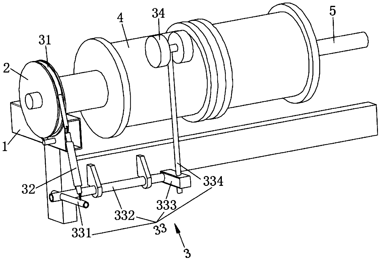
[0026] refer to figure 1 , this embodiment discloses a tensioning device for a feeding mechanism of a warp knitting machine, including a bracket 1 , a speed regulating disk 2 , a tensioning conduction assembly 3 , a feeding roller 4 and a rotating shaft 5 . The rotating shaft 5 is arranged on the bracket 1 . The feeding roller 4 is sleeved on the rotating shaft 5 . One end of the tension conduction assembly 3 capable of adjusting the rotational speed of the speed regulating disk 2 is connected to the speed regulating disk 2 , and the other end is in contact with the feeding roller 4 .

[0027] The rotating shaft 5 is rotatably fitted with a fixed sleeve, and the fixed sleeve is installed on the bracket 1 .

[0028] The rotating shaft 5 drives the feeding roller 4 to rotate, the cloth on the feeding roller is reduced, the radius of the cylinder formed by the cloth is reduced, and the output linear speed is reduced. The rotation speed of the cloth is accelerated with the redu...

Embodiment 2

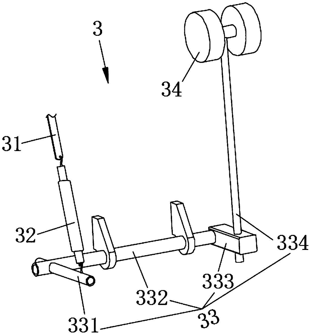
[0036] The elastic connector 32 is a compressed air cylinder (not shown in the figure). The compressed gas cylinder includes a cylinder body (not shown in the figure) and a push rod (not shown in the figure) arranged in the cylinder body. The output end of the push rod is connected to the first connecting pipe 331 . The cylinder is connected to the elastic resistance piece 31 .

[0037] When the amount of cloth wound on the feeding roller 4 increases, the second connecting pipe 334 rotates, and the first connecting pipe 331 is driven to rotate through the connecting shaft 332, and then the push rod is pulled out from the cylinder to form a negative pressure in the cylinder; When the cloth wound on the roller 4 decreases, the negative pressure formed in the cylinder will draw back the push rod. When the cloth increases or decreases, the positive and negative pressure formed by the cylinder will increase or decrease the frictional force between the elastic resistance sheet 31 ...

Embodiment 3

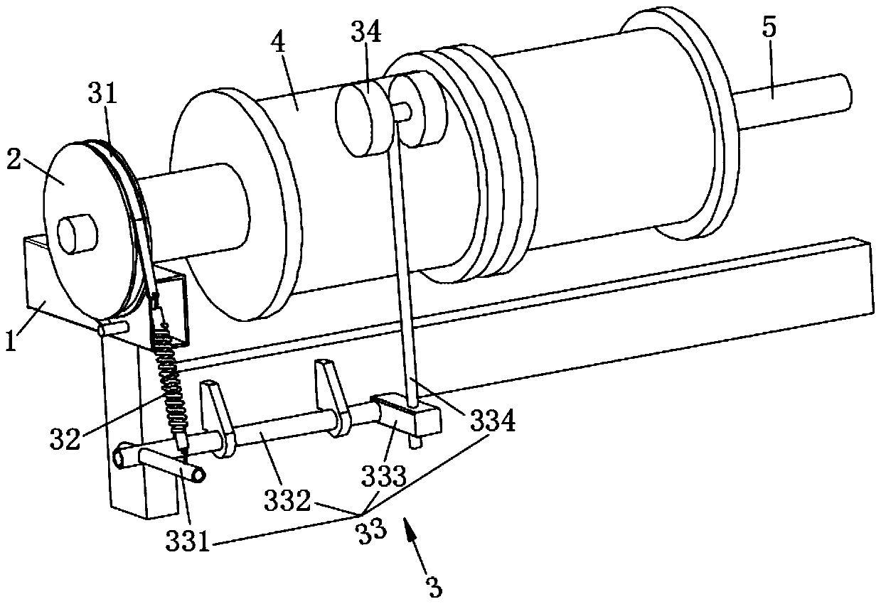
[0039] refer to image 3 The difference between the second embodiment and the first embodiment is that the elastic connecting member 32 is a spring. When one end of the spring is subjected to an external force, under the action of its elasticity, the change range of the external force at the other end decreases, and the vibration amplitude of the components connected to the other end decreases, which effectively prevents the elastic resistance sheet 31 from falling off due to severe external impact force , secondly, the spring has good elasticity and simple structure, and the elastic connector 32 is made of spring, which has the highest comprehensive cost performance.


PUM


Abstract

The invention discloses a warp knitting machine feeding mechanism tensioning device. The device comprises a support, a speed adjusting plate, a tensioning conduction assembly, a feeding roller and a rotating shaft, wherein the rotating shaft is arranged on the support; the feeding roller is connected with the rotating shaft in a sleeving mode; and one end of the tensioning conduction assembly capable of adjusting the rotation speed of the speed adjusting plate is connected with the speed adjusting plate, and the other end of the tensioning conduction assembly is in contact connection with thefeeding roller. The device has the advantages that under the condition that the output power of a motor is constant, the resistance of the speed adjusting plate is reduced, and the rotating speed of the rotating shaft is higher, and meanwhile, the radius of a cylinder wrapped by cloth is reduced, and the length of the output cloth in unit time is not changed, so that the continuous stability of production is guaranteed, and the situation that the cloth is broken or wrinkled is avoided.

Description

technical field [0001] The invention relates to the technical field of warp knitting machine feeding, in particular to a tensioning device for a warp knitting machine feeding mechanism. Background technique [0002] The warp knitting machine is a kind of warp knitting equipment, which loops one or several groups of parallel yarns according to the warp and weft structure and forms a knitted fabric machine. When the feeding roller of the warp knitting machine transmits the cloth, as the cloth decreases, the radius of the cylinder wrapped by the cloth decreases, and when the output speed of the motor remains unchanged, the speed of the feeding roller remains unchanged, resulting in the same time, The output length of the fabric is reduced, and the receiving speed of the subsequent process is constant. In actual production, the fabric is prone to breakage under this situation, which will cause production to stop, affect the production progress, and reduce production efficiency. ...

Claims


Application Information

Patent Timeline
IPC IPC(8): B65H16/10B65H23/182
CPCB65H16/10B65H23/1825B65H2701/1133B65H2701/174
Inventor 方华保
Owner 安庆市华兴纤维制品有限公司
Why Eureka
Try Eureka