Crankshaft and compressor therewith

A crankshaft and eccentricity technology, which is applied in the field of compressors, can solve the problems of compressor performance degradation, cumbersome compressor crankshaft assembly process, and reduced universality of compressor crankshafts.

Active Publication Date: 2017-10-03
GREE ELECTRIC APPLIANCES INC +1
View PDF5 Cites 0 Cited by
  • Summary
  • Abstract
  • Description
  • Claims
  • Application Information

AI Technical Summary

Problems solved by technology

[0003] Based on this, it is necessary to provide a crankshaft and a compressor with the problems that the performance of the compressor is reduced by adding main and auxiliary balance weights to the existing compressor crankshaft, the assembly process of the compressor crankshaft is cumbersome, and the universality of the compressor crankshaft is reduced.

Method used


Image

  • Crankshaft and compressor therewith
  • Crankshaft and compressor therewith
  • Crankshaft and compressor therewith

Examples


Embodiment Construction

[0036] In order to make the technical solution of the present invention clearer, the present invention will be further described in detail below in conjunction with the accompanying drawings and specific embodiments.

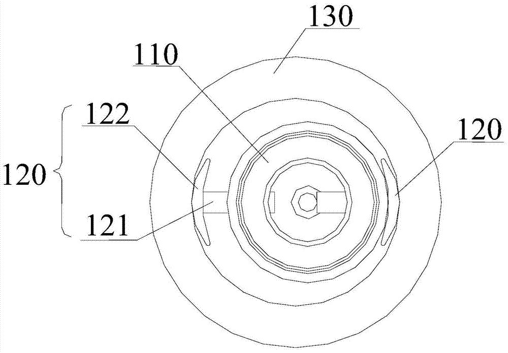
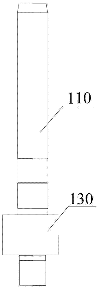
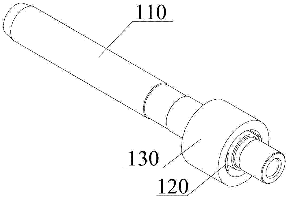
[0037] see Figure 1 to Figure 3 , taking the crankshaft of the present invention including two eccentricity adjustment devices 120 as an example, the crankshaft of the present invention will be described. Wherein, the crankshaft includes a crankshaft body 110 and an eccentric portion disposed on the crankshaft body 110 . The eccentric part includes two eccentric adjustment devices 120 . Meanwhile, the crankshaft body 110 is provided with two mounting holes 111 distributed along the circumferential direction. It should be noted here that the installation holes 111 correspond to the eccentricity adjustment devices 120 one by one.

[0038] Wherein, the eccentricity adjusting device 120 is provided with a connecting portion 121 , and is inserted into the mountin...


PUM


Abstract

The invention discloses a crankshaft and a compressor having the crankshaft, wherein the crankshaft includes a crankshaft body and an eccentric part arranged on the crankshaft body; more than two installation holes distributed along the circumferential direction are arranged on the crankshaft body; the eccentric part includes two More than one eccentricity adjustment device; the eccentricity adjustment device is provided with a connecting part, and is inserted into the mounting hole through the connecting part to connect with the crankshaft body, and the eccentricity adjustment device is suitable for moving along the radial direction of the crankshaft body; when the crankshaft rotates, the sleeve The vector sum of the rotational inertial force of the rollers arranged outside the eccentric portion and the rotational inertial forces of each eccentricity adjusting device is equal to zero. It effectively solves the problems of complicated assembling process of the existing compressor crankshaft and reduced commonality of the compressor crankshaft.

Description

technical field [0001] The invention relates to the field of compressors, in particular to a crankshaft and a compressor with the crankshaft. Background technique [0002] At present, due to the existence of an eccentric circle on the crankshaft of the compressor, the center of mass of the eccentric part of the crankshaft and the roller does not coincide with the rotation center of the main shaft, so a rotational inertial force will be generated during the operation of the compressor. Usually, the balance of the rotational inertial force is achieved by adding the main and auxiliary balance weights of the motor, and the cooperation between the main and auxiliary balance weights and the eccentric part of the crankshaft. However, the cooperation between the main and auxiliary balance weights and the eccentric part of the crankshaft cannot achieve a complete balance of the rotational inertial force, and the imbalance of the rotational inertial force will increase the winding deg...

Claims


Application Information

Patent Timeline
Patent Type & Authority Patents(China)
IPC IPC(8): F04B39/00F16C3/12
Inventor 程剑国范少稳潘登崔雪梅詹大强
Owner GREE ELECTRIC APPLIANCES INC
Why Eureka
Try Eureka