Clutch unit

A clutch and side clutch technology, applied in the direction of clutch, one-way clutch, automatic clutch, etc., can solve the problems of noise, unstable behavior of the outer center spring 119, etc., and achieve the effect of preventing noise.

Active Publication Date: 2015-08-12
NTN CORP
View PDF7 Cites 7 Cited by
  • Summary
  • Abstract
  • Description
  • Claims
  • Application Information

AI Technical Summary

Problems solved by technology

Here, one locking portion 119a is formed by bending one piece side portion in the strip width direction, and the other locking portion 119a is formed by bending the other piece side portion in the strip width direction. Therefore, when the input torque acts, it is easy to generate a moment force such that the other locking portion 119a is rotated with one locking portion 119a as a fulcrum, resulting in instability of the behavior of the outer centering spring 119, which There may be slight noise as a cause

Method used


Image

  • Clutch unit
  • Clutch unit
  • Clutch unit

Examples


Embodiment Construction

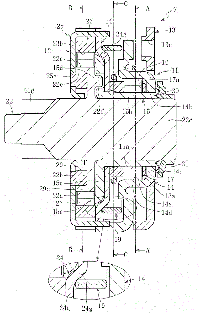
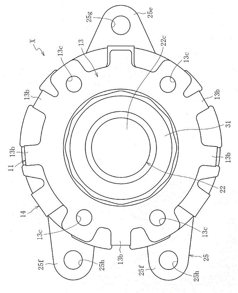
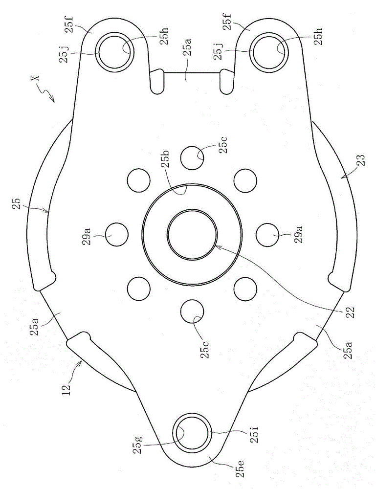
[0099] figure 1 is a longitudinal sectional view showing the overall structure of the clutch unit X in the embodiment of the present invention, figure 2 Yes figure 1 Right side view of clutch unit X shown, image 3 Yes figure 1 Left side view of clutch unit X shown, Figure 4 is along figure 1 Transverse sectional view of A-A, Figure 5 is along figure 1 Lateral cut view of the B-B line. In addition, FIGS. 6 to 18 are diagrams showing main components of the clutch unit X. As shown in FIG. Figure 19~ Figure 31 It is a figure which shows the assembly state of the main structural components of the clutch unit X.

[0100] The clutch unit X is incorporated in, for example, an automotive seat lifter that performs height adjustment of the seat by lever operation (refer to Figure 38 , Figure 39a and Figure 39b )middle. like Figure 1 to Figure 5 As shown, the clutch unit X has a structure in which a lever-side clutch portion 11 provided on the input side and a ...


PUM


Abstract

Provided is a clutch unit, comprising: a lever-side clutch portion (11) for controlling transmission and interruption of rotational torque to an output side through lever operation; and a brake-side clutch portion (12) for transmitting torque input from the lever-side clutch portion (11) to the output side and for interrupting torque reversely input from the output side, wherein: the lever-side clutch portion (11) comprises an outer centering spring (19) provided between a lever-side outer ring (14) to be rotated through the lever operation and a cover (24) restricted in rotation, for accumulating an elastic force obtained by torque input from the lever-side outer ring (14) and for restoring the lever-side outer ring (14) to a neutral state with the accumulated elastic force through releasing of the torque input from the lever-side outer ring (14); the cover (24) comprises an inclined portion (24g) which abuts on the outer centering spring (19) and swells to the outer centering spring (19) side; and a rounded corner surface (24g 1 ) situated at an outermost diameter of the inclined portion (24g) is formed into a shape for controlling an amount of axial movement of the outer centering spring (19) when the outer centering spring (19) is restored to an initial state through the releasing of the torque input from the lever-side outer ring (14).

Description

[0001] This application is a divisional application of an invention patent application with an application date of March 1, 2011, an application number of 201180013972.9, and an invention title of "clutch unit". technical field [0002] The present invention relates to a lever-side clutch unit that transmits rotational torque from an input side to an output side, and a brake-side clutch that transmits rotational torque from an input side to an output side and blocks reverse input torque from an output side. clutch unit. Background technique [0003] In general, in a clutch unit using engaging elements such as cylindrical rollers or balls, a clutch portion is arranged between an input side member and an output side member. The structure of the clutch part is such that the transmission and interruption of the input torque are performed by engaging and disengaging engaging members such as cylindrical rollers and balls in the wedge-shaped gap formed between the aforementioned in...

Claims


Application Information

Patent Timeline
Patent Type & Authority Applications(China)
IPC IPC(8): F16D41/10F16D41/064B60N2/16B60N2/44B60N2/90
CPCF16D41/105B60N2/444B60N2/168F16D43/02B60N2/1615B60N2/167F16D41/086B60N2/938F16D67/02
Inventor 佐藤光司斋藤隆英川合正浩矶田康二久保田尚史峰野弓子滨崎浩光
Owner NTN CORP
Why Eureka
Try Eureka