
Object recognition device

A technology for object recognition and objects, applied in scene recognition, measurement devices, optical observation devices, etc.

Active Publication Date: 2019-06-04
TOYOTA JIDOSHA KK
View PDF14 Cites 0 Cited by
  • Summary
  • Abstract
  • Description
  • Claims
  • Application Information

AI Technical Summary

Problems solved by technology

However, because these areas are fixed to the relative orientation of detected objects, it is possible to misjudge different objects detected in a curve lane as the same object

Method used


Image

  • Object recognition device
  • Object recognition device
  • Object recognition device

Examples


Embodiment approach 1

[0046] First, refer to Figure 1 to Figure 8 Embodiment 1 of the present invention will be described.

[0047] 1. Composition of object recognition device

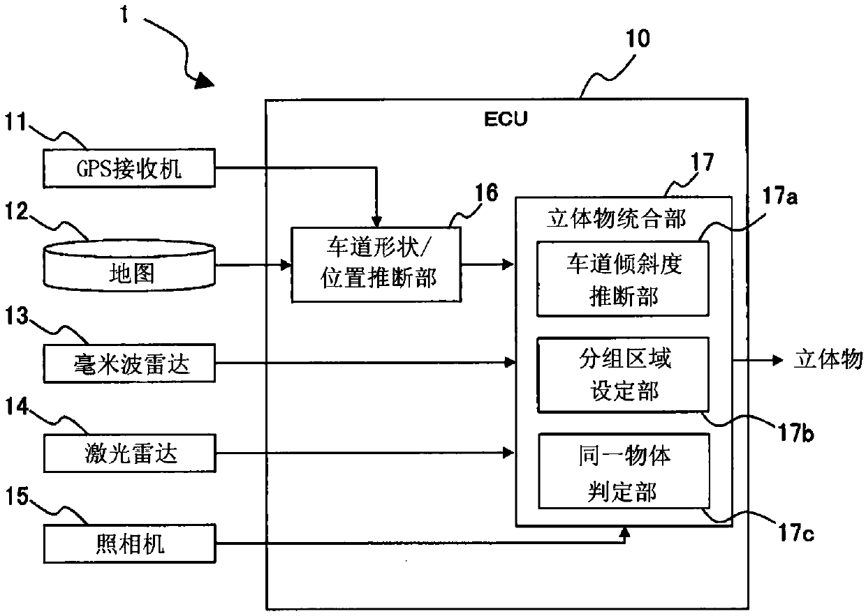
[0048] figure 1 It is a block diagram showing the configuration of the object recognition device according to Embodiment 1 of the present invention. figure 1 The illustrated object recognition device 1 is mounted on a vehicle, and is used to recognize three-dimensional objects existing in front, side and rear of the vehicle. Three-dimensional objects to be recognized are, for example, moving objects such as pedestrians, bicycles, and automobiles, and fixed objects such as trees, utility poles, buildings, and road structures. Road structures include, for example, structures (hereinafter, also referred to as "roadside objects") installed on roadsides such as guardrails, road signboards, retaining walls, and soundproof walls. In this specification, the vehicle on which the object recognition device 1 is mounted is also re...

Embodiment approach 2

[0084] Next, refer to Figure 9 to Figure 10 Embodiment 2 of the present invention will be described.

[0085] 1. Composition of object recognition device

[0086] Figure 9 It is a block diagram showing the configuration of the object recognition device according to Embodiment 2 of the present invention. Figure 9 The composition of the object recognition device 2 shown is the same as figure 1 The object detection device 1 shown has basically the same structure. Description of the same configuration is omitted. In this manual, with the equipped with figure 1 The vehicle of the object recognition device 1 shown will be equipped with Figure 9 The vehicle of the object detection device shown is also referred to as "own vehicle OV".

[0087] andfigure 1 The object recognition device 1 shown is different, Figure 9 The illustrated object recognition device 2 includes a roadside object determination portion 18 . The roadside object determination unit 18 is configured to r...


PUM


Abstract

The invention relates to an object recognition device, and provides the technology which can prevent a condition that different objects detected in a curved lane are wrongly determined as the same object. A solid object fusion portion includes a lane slope estimation portion, a grouping area set portion and an identity determination portion. The lane slope estimation portion performs estimate processing to estimate a lane slope angle theta in a detecting position of a solid object detected by an autonomous recognition sensor. The grouping area set portion performs setting processing to set a grouping area GA used in determination processing in the identity determination portion. Based on the grouping area GA, the identity determination portion determines whether or not the solid object detected by a certain autonomous recognition sensor is identical to the solid object detected by an autonomous recognition sensor which is different from the certain autonomous recognition sensor.

Description

technical field [0001] The invention relates to an object recognition device. Background technique [0002] Japanese Patent No. 5812064 discloses an object recognition device in which an area centered on the position of a first object detected by a millimeter-wave radar and a second object detected based on an image captured by a vehicle-mounted camera In the case where the area centered at the position of is overlapped, it is determined that the first object and the second object are the same object. [0003] Patent Document 1: Japanese Patent No. 5812064 [0004] In the object recognition device described above, an error due to the characteristics of the millimeter-wave radar is considered for the area centered on the position of the first object. In addition, an error due to the characteristics of the vehicle-mounted camera is taken into account for the region centered on the position of the second object. However, since these areas are fixed to the relative directions...

Claims


Application Information

Patent Timeline
IPC IPC(8): G01S13/93G01S13/931
CPCG01S13/931G01S13/867G01S13/865G06T2207/30256G06T7/60G06V20/588G06V20/58G01S13/50G06T7/73G01S13/06G06T2207/30261B60R2300/302B60R2300/301
Inventor 小森照元
Owner TOYOTA JIDOSHA KK
Learn More