Driving device provided with piezoelectric element deterioration detection circuit and deterioration detection method

A piezoelectric element and driving device technology, which can be applied to piezoelectric or electrostrictive device parts, piezoelectric effect/electrostrictive or magnetostrictive motors, and electrical components, etc., can solve the problem of cost increase, Complex structure, etc.

Pending Publication Date: 2021-11-12
FUJIKIN INC
View PDF3 Cites 0 Cited by
  • Summary
  • Abstract
  • Description
  • Claims
  • Application Information

AI Technical Summary

Problems solved by technology

[0014] In Patent Document 3, although the deterioration of the piezoelectric element can be detected, it is necessary to provide a circuit for abnormality detection other than the drive circuit during normal operation, and there is a problem that the structure becomes complicated and the cost increases.
In addition, b

Method used


Image

  • Driving device provided with piezoelectric element deterioration detection circuit and deterioration detection method
  • Driving device provided with piezoelectric element deterioration detection circuit and deterioration detection method
  • Driving device provided with piezoelectric element deterioration detection circuit and deterioration detection method

Examples


Embodiment 1

[0105] The experimental results are shown below, showing the effectiveness of the present invention.

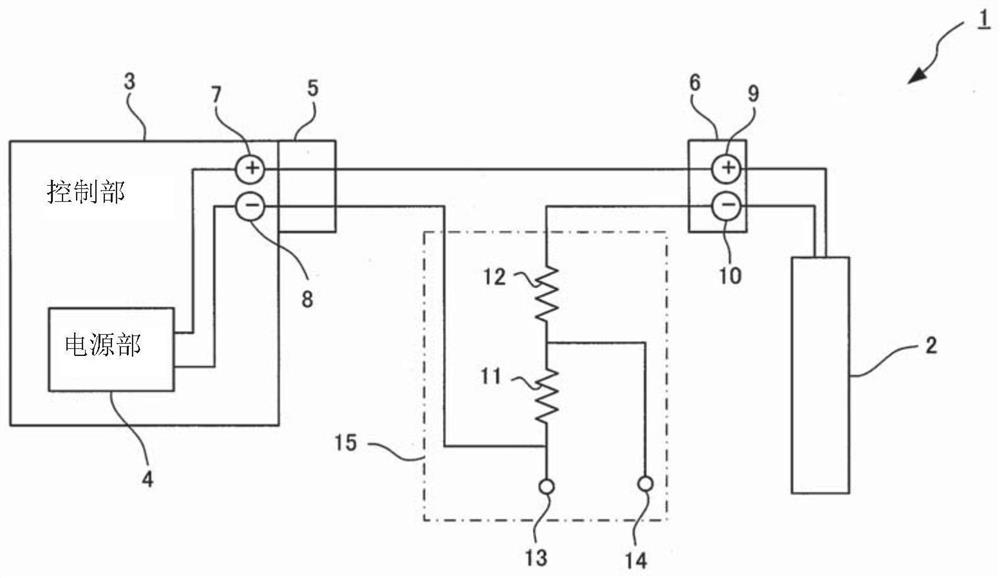
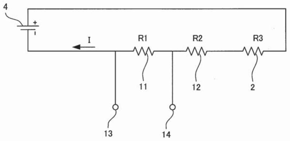
[0106] exist figure 1 In the pressure-type flow control device having the structure shown, the voltage across the first resistor 11 (the voltage between the first terminal 13 and the second terminal 14 ) is measured while a DC voltage of 140 V is supplied to the piezoelectric element 2 . , to calculate its average value. The resistance values ​​of the first resistor 11 and the second resistor 12 are respectively set to 10 kΩ and 39 kΩ. For voltage measurement, a tester (Digital Multimeter 289, manufactured by Fluke Corporation) and a data recorder (Mobile recorder MV200, manufactured by Yokogawa Electric Corporation) were used.

[0107] In each of the three pressure-type flow control devices (ID1 to ID3) of the same type of piezoelectric element used, after opening and closing the control valve 3 million times, use the above two types of measuring devices to measure Measu...

Embodiment 2

[0112] For pressure type flow control devices using different types of piezoelectric elements, in the same manner as in Example 1, the voltage across the first resistor 11 was measured, and the resistance value of the piezoelectric element used in each pressure type flow control device was calculated. . The result is as Figure 7 shown.

[0113] Figure 7 Changes in resistance values ​​calculated from measured values ​​related to the respective piezoelectric elements are schematically shown. exist Figure 7 In , the vertical axis represents the resistance value (calculated value) of the piezoelectric element, and the horizontal axis represents the driving time of the control valve. As the driving time increases, the number of times the control valve is opened and closed (the number of voltage applications to the piezoelectric element) also increases. The solid line is the measurement result of the control valve provided with the moisture adsorbent, and the dotted line is ...


PUM


Abstract

To provide a driving device provided with a piezoelectric element deterioration detection circuit and a deterioration detection method which enable detection of deterioration of a piezoelectric element for use in the driving device without stopping a normal operation of the driving device. A driving device 1 is provided with a piezoelectric element 2, a power source 3, a first resistor 11, a second resistor 12, a measurement unit, and a control unit, wherein: the resistance values of the first and second resistors are smaller than the insulating resistance value of the piezoelectric element; the measurement unit measures a voltage across the both ends of the first resistor (voltage between a first terminal 13 and a second terminal 14) in a state where a prescribed voltage is supplied from the power source; and the control unit 3 calculates the resistance value of the piezoelectric element from a voltage value acquired through the measurement carried out by the measurement unit, and determines whether deterioration has occurred in the piezoelectric element on the basis of the calculated resistance value.

Description

technical field [0001] The present invention relates to a driving device provided with a degradation detection circuit of a piezoelectric element used as a driving source of a driving device such as an actuator, and a method for detecting degradation of a piezoelectric element, and in particular to a semiconductor manufacturing facility or a chemical factory. Among them, the control device used for supplying fluid such as gas is a pressure-type flow rate control device provided with a degradation detection circuit of a piezoelectric element, and a method for detecting degradation of a piezoelectric element of a pressure-type flow rate control device. Background technique [0002] There are known pressure-type flow control devices used for supplying fluids such as gases in semiconductor manufacturing equipment, chemical plants, and the like (Patent Documents 1, 2, etc.). In this pressure type flow control device, a control valve (valve) using a piezoelectric element (Piezo el...

Claims


Application Information

Patent Timeline
IPC IPC(8): H02N2/06G01N27/00H01L41/04
CPCH02N2/06H10N30/80F16K31/007F16K37/0041G01N27/00H10N30/802F16K37/0083G01N27/028
Inventor 日高敦志杉田胜幸中谷贵纪西野功二池田信一
Owner FUJIKIN INC
Why Eureka
Try Eureka