Clutch unit

A clutch and side clutch technology, applied in clutches, one-way clutches, automatic clutches, etc., can solve the problems of difficult rotation resistance, deterioration over time, surface pressure rise of cylindrical roller 127, etc., to prevent noise and reduce elapsed time. Sex-reducing effect

Active Publication Date: 2015-04-22
NTN CORP
View PDF6 Cites 4 Cited by
  • Summary
  • Abstract
  • Description
  • Claims
  • Application Information

AI Technical Summary

Problems solved by technology

[0018] However, since the material constituting the friction ring 129 deteriorates over time, it is difficult to maintain the interference with the output shaft 122
As a result, when an excessive torque is applied to the output shaft 122, when the locked state of the brake-side clutch portion 112 is released by operating the lever in the lever-side clutch portion 111, the friction ring 129 is connected to the output shaft. Since the interference of 122 is reduced, it is difficult to impart a predetermined rotational resistance to the output shaft 122. Therefore, there is a possibility that the surface pressure of the cylindrical roller 127 increases and a large vibration occurs.
Such vibration may cause discomfort to the occupant who adjusts the seat up and down by operating the lever.

Method used


Image

  • Clutch unit
  • Clutch unit
  • Clutch unit

Examples


Embodiment Construction

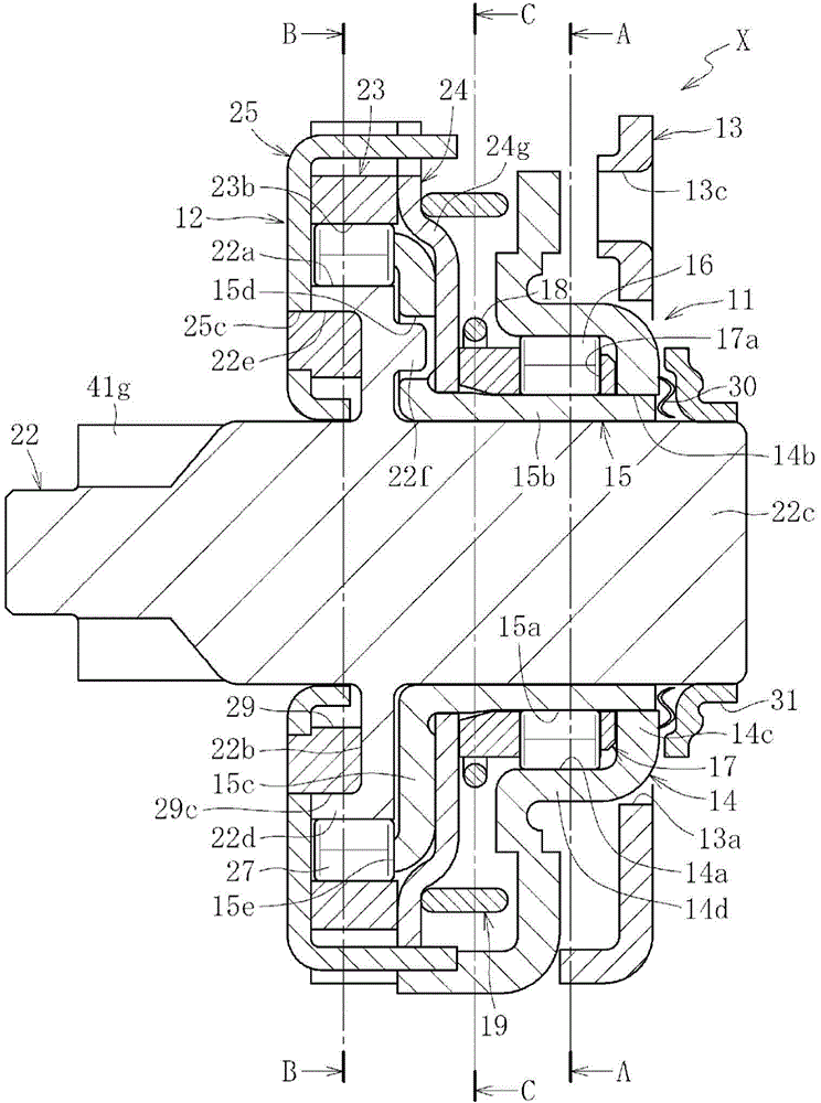
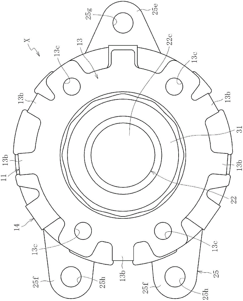
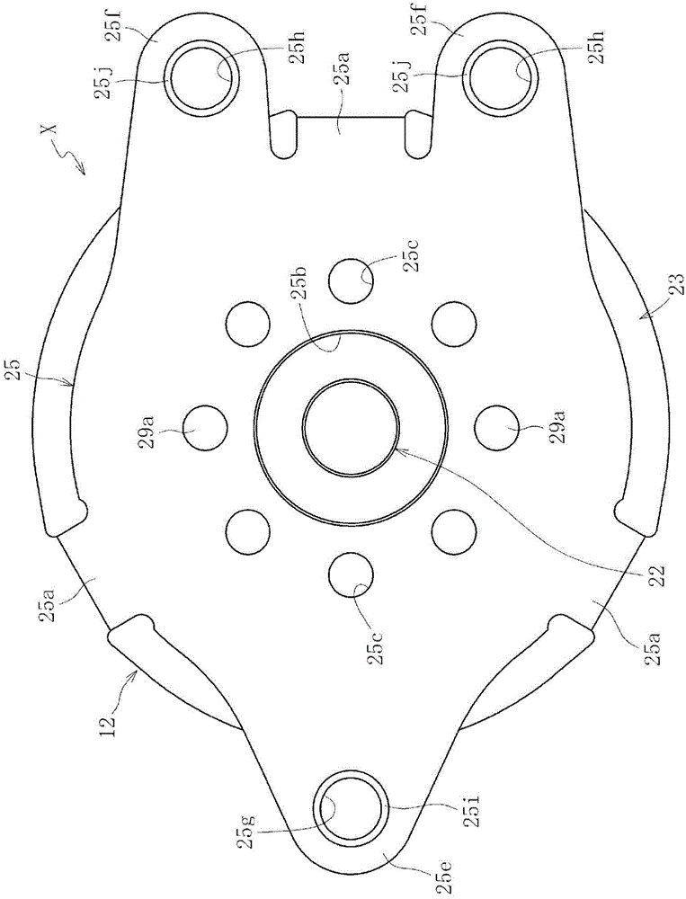
[0097] figure 1 is a longitudinal sectional view showing the overall structure of the clutch unit X in the embodiment of the present invention, figure 2 yes figure 1 Right side view of clutch unit X shown, image 3 yes figure 1 Left side view of clutch unit X shown, Figure 4 is along figure 1 Transverse sectional view of A-A, Figure 5 is along figure 1 Transverse sectional view of the B-B line. In addition, FIGS. 6 to 18 are diagrams showing main components of the clutch unit X. As shown in FIG. Figure 19 ~ Figure 3 1 is a diagram showing an assembled state of main components of the clutch unit X. As shown in FIG.

[0098] The clutch unit X is incorporated in, for example, an automotive seat lifter that performs height adjustment of the seat by lever operation (refer to Figure 32 , Figure 33a and Figure 33b )middle. Such as Figure 1 to Figure 5 As shown, the clutch unit X has a structure in which a lever-side clutch part 11 provided on the input side ...


PUM


Abstract

Provided is a clutch unit, comprising: a lever-side clutch portion for controlling transmission and interruption of rotational torque to an output side through lever operation; and a brake-side clutch portion for transmitting torque input from the lever-side clutch portion to the output side and for interrupting torque reversely input from the output side, wherein: the lever-side clutch portion comprises an outer centering spring (19) provided between a lever-side outer ring to be rotated through the lever operation and a cover (24) restricted in rotation, for accumulating an elastic force obtained by torque input from the lever-side outer ring and for restoring the lever-side outer ring to a neutral state with the accumulated elastic force through releasing of the torque input from the input-side member, the outer centering spring (19) comprising a band plate-like spring member having a C-shape, the cover (24) comprising an inclined portion (24g) which abuts on the outer centering spring (19) and swells to the outer centering spring (19) side; and under a state in which the outer centering spring (19) is assembled, an inner diameter of the outer centering spring (19) is arranged on an outer side of an outermost diameter of the inclined portion (24g) of the cover (24).

Description

[0001] This application is a divisional application of an invention patent application with an application date of February 10, 2011, an application number of 201180009394.1, and an invention title of "clutch unit". technical field [0002] The present invention relates to a lever-side clutch unit that transmits rotational torque from an input side to an output side and a brake-side clutch unit that transmits rotational torque from an input side to an output side and blocks reverse input torque from an output side. clutch unit. Background technique [0003] In general, in a clutch unit using engaging elements such as cylindrical rollers or balls, a clutch portion is arranged between an input side member and an output side member. The structure of the clutch part is such that the transmission and interruption of the input torque are performed by engaging and disengaging engaging members such as cylindrical rollers and balls in the wedge-shaped gap formed between the aforement...

Claims


Application Information

Patent Timeline
Patent Type & Authority Applications(China)
IPC IPC(8): F16D41/08F16D41/10F16D43/02B60N2/90
CPCF16D43/02F16D41/088B60N2/167F16D41/105B60N2/444B60N2/1615B60N2/168B60N2/938
Inventor 川合正浩矶田康二峰野弓子
Owner NTN CORP
Why Eureka
Try Eureka